Architectured sheets by localized laser treatment¶
morphogen.laser simulates and optimizes metal sheets architectured by a laser: a beam
(or two aligned beams, one on each face) follows a path that hardens — or softens,
carburizes, nitrides, alloys — narrow tracks of the sheet; the pattern of the tracks
gives the sheet a behaviour that neither phase has alone (Bouaziz, Bréchet & Embury
2008; Brechet & Embury 2013). The module follows the PhD thesis of Zhige Wang
(Architecturation de tôles métalliques par traitement laser localisé, HESAM
Université, PIMM, 2022) and the ANR project SCOLASTIC (ANR-16-CE08-0009: “systematic
computational optimisation and local laser processing for steel-based architectured
materials”), whose loop it closes: a process model gives the hardness that a path leaves
in the sheet, a finite element model gives the response of the specimen, an optimizer
changes the path.
The formulas are in theory, the classes and functions in the API reference. This page reads in four parts:
the model: the choices of a study, the chain of models and what checks them (§1 to §3), and how to run it (§12, Use);
the results on tensile specimens and on other structures: the first results, the fracture of the martensite, a crack, a corner, the anisotropy and other materials (§4, §5, §10 and §11);
the design of the treated pattern: cell by cell, by densities, as laser paths, and with morphoGen’s morphologies at the scale of the spot (§6 to §8, §14);
the geometric work hardening of corrugated tracks, where it works, and the crossed families of straight tracks that lock (§15 to §17).
§9 places the module among related work and §13 states its limits; the literature survey gathers the materials that a laser treatment turns into two-phase sheets.
1. The choices of a study¶
The thesis left six choices open; the module takes each as an input, with defaults that the literature and the simulations below support.
Choice |
Default |
Alternatives in the module |
Why |
|---|---|---|---|
Load case and objective |
uniaxial tension of a flat specimen along the rolling direction; maximize the strength–ductility product |
the energy absorbed up to necking, |
hardening leaves Young’s modulus unchanged, so stiffness and elastic buckling cannot improve; the pattern acts on yielding, strain hardening and necking, which tension measures cheaply (Considère’s maximum of the force); the case of the thesis and of the literature (Fraser et al. 2018a, 2020; Wang et al. 2023; Breukelman et al. 2022). The product alone favours the untreated sheet: the yield constraint fixes the strength level at which ductility is sought |
Base material |
MS1500 annealed at 850 °C (ferrite–pearlite, 0.23 C, 1.7 Mn, 1 mm; 167 HV, |
AISI 430 (0.5 mm), DP1180 (soft tracks), any material given as a mapping |
the largest contrast of the hard tracks (laser martensite of about 500 HV, |
Treatment |
transformation hardening (martensite), peak between |
carburizing from a graphite coating, nitriding under nitrogen, alloying from a pre-placed coating (melt pool); tempering of martensitic sheets |
no coating, no melting needed in a C–Mn steel; carburizing raises the contrast of low-carbon steels (430: +130 % HV, thesis ch. 4) but needs melting (columnar grains, oxide: argon); nitrogen dissolves in iron only with chromium (0.04 wt% in Fe, 0.3 in Fe–18Cr at 1 atm) |
Specimen |
flat dog-bone, parallel part 30 × 5 × 1 mm, fillets of radius 6 mm, grips 10 mm wide; a DIC-like extensometer over 25 mm |
strip (clamped or free ends), any dimensions |
the specimens of Wang (2022, ch. 5): one track 1.2 mm wide is 24 % of the section |
Laser configuration |
symmetric: a Gaussian fibre beam (150 W, 1 mm) above and a top-hat diode (100 W, 1.2 mm) below, together, 10 mm/s |
single (the upper face), the same beam on both faces |
the platform of Wang et al. (2022): through 0.5 mm the gap of peak temperature is about 10 K with two beams and 260 K with one; the tracks are then through-thickness reinforcements, which unbend together |
Pattern (laser path) |
one corrugated track |
straight, oblique, Fourier waveforms (free shapes), crossed families, honeycombs, any polylines |
the geometric work hardening of corrugations that unbend (Bouaziz 2013; Fraser et al. 2014, 2018a): |
Process constraints enter as constraints of the optimization: the smallest gap between tracks (closer tracks temper each other; Wang waited at least 30 s between neighbouring tracks), the smallest radius of curvature of a track (the cycles of the model are those of a straight track: radii above the heated width; and the kinematics of the robot), the length of the path in the specimen (time and energy).
2. The chain of models¶
Heat (
laser.heat). A beam of absorbed powerPmoving atvon a plate of thicknessh: the plane profile of the beam (Gaussian or top hat) spread by the heat kernel, images through the thickness for adiabatic faces, a second beam on the lower face, surface losses; the quasi-steady fieldT(ξ, y, z)is one integral over the delay, a product of matrices on grids. Its limits are Rosenthal’s point source and Rykalin’s line source with losses. A straight track then imposes a thermal cycleT(t; d, z)on each point at the distancedof its axis and the depthz(TrackKernel). Transient finite volumes of the whole blank (implicit, split along x, y and z) check the quasi-steady cycles and give the heat that the previous tracks leave.Metallurgy (
laser.metallurgy). C–Mn steels: austenite at the peak of each cycle (lever rule with theA3line,Ac1andAc3of Andrews plus a superheat of the laser heating rates), martensite on cooling (Koistinen–Marburger below Andrews’sMsof the austenite’s carbon; bainite beyond a critical cooling timet8/5), hardnesses of Maynier et al. (1978), tempering of martensite by the Hollomon–Jaffe parameter accumulated by additivity. AISI 430: the hardness gained as a function of the peak temperature (calibrated on the thesis), tempered the same way. Carburizing, nitriding and alloying: the coating (or nitrogen, Sieverts) mixed into the melt pool of each track by mass balance.Strength (
laser.materials). The tensile properties of each state against its hardness (measured: the base and the fully treated 430 at 15 and 20 kJ/m, the carburized 430, the annealed MS1500 and its martensite), interpolated, extrapolated by Pavlina & Van Tyne’s correlations; each point gets the Ludwik (or Voce) law fitted toR_p,R_mandA_gby Considère’s condition.Treatment of a path (
laser.process). The tracks in their order: the distance of each Gauss point to a track gives its cycle at each layer; untouched points take the tabulated response of the track, the others (the neighbours of earlier tracks) integrate their cycle — the tempered rings, the re-hardened crossings.Mechanics (
laser.mechanics,laser.bending). The specimen as a membrane of bilinear quadrilaterals in plane stress, each Gauss point a stack of layers with their own flow laws; large rotations by a corotational update of the logarithmic strain increments (the unbending of the corrugations), von Mises plasticity by a radial return with the thickness strain fromσ33 = 0, the consistent tangent of the Kirchhoff stress; displacement-controlled tension to past the maximum force. In several directions, the pattern is turned by the opposite angle and repeated at its spacing over the sheet before the specimen is cut. Three-point bending: the strip as a statically determinate beam whose sections are grids of fibres (across the width, through the layers) with their own flow laws, the neutral axis from the axial equilibrium (off the mid-plane under a one-sided treatment), the moment–curvature of each section inverted for the moment of the load, the deflection by virtual work.Optimization (
laser.design). Parameters of the pattern and of the beams between bounds; grid, Nelder–Mead, differential evolution, genetic algorithm, or Bayesian optimization (a Gaussian process of the penalized costs, the expected improvement): a few tens of evaluations of a few seconds each.
3. Checks¶
The tests (tests/test_laser.py) compare with closed forms and independent
computations: the moving source with Rosenthal’s thick-plate and Rykalin’s thin-plate
solutions (2e-4); the energy P/v of a cross-section far behind the beam (2e-3); the
transient finite volumes with the quasi-steady cycles (4 %); Andrews’s and Maynier’s
values (the annealed MS1500: 173 HV computed, 167 ± 6 measured); the lever rule at A1
(the pearlite at once) and A3; Koistinen–Marburger after a quench; the additivity of
the Hollomon–Jaffe parameter (an isothermal hold in 50 steps equals the formula to
1e-6); Sieverts’s solubility; the mass balance of a carburized melt; the flow laws
against the tensile properties they are fitted to (1e-6); the arc length and curvature
of corrugated tracks; the membrane in uniaxial tension against the exact response of a
homogeneous strip (2e-4 on the curve, R_m to 1e-4, A_g to 2e-3); the tangent
against finite differences (2e-5); a rigid rotation that turns the stresses and leaves
the plastic strain; two bands along the load at equal strain (5e-3).
Against the experiments of the thesis (measured values in brackets):
AISI 430, 0.5 mm, double laser: at 50 + 50 W the mid-thickness stays below
Ac1[below Ac1]; at 100 + 100 W the track reaches the melting point through the thickness [peak near Tm]; at 150 + 100 W it melts [full fusion at 25 kJ/m].Annealed MS1500, 1 mm, 150 + 100 W, absorptivity 0.55: austenitized through the thickness over 1.14 mm [tracks of 1.2 mm, nearly fully martensitic].
AISI 430 fully treated by ten tracks at 1 mm pitch, double laser under argon, after the hardness gained at 1300 °C and the tempering of the gain were fitted to the mean hardness of these sheets (212, 240 and 235 HV computed [211.5, 241.8, 233.6]):
Energy
R_p(MPa)R_m(MPa)A_g(%)15 kJ/m (75 + 75 W)
468 [488.7]
626 [623.5]
15.6 [15.52]
20 kJ/m (100 + 100 W)
525 [539.7]
704 [702.5]
13.7 [13.65]
25 kJ/m (150 + 100 W)
507 [513.0]
682 [680.6]
14.1 [13.91]
The tempering of earlier tracks by the next ones, which the thesis held responsible for the drop from 20 to 25 kJ/m, gives it here too.
4. First results¶
All simulated (elements of 0.5 mm, four layers; the uniform elongation moves by up to 15 % on elements of 0.25 mm, the trends do not).
Corrugated martensite in annealed MS1500 (one track, about 28 % of the section;
Wang et al. 2023 found, at 24 %, that a larger height over period gains necking strain
and loses yield and tensile strength; their tests in brackets, R_p/R_m/A):
Track |
|
|
|
energy (MJ/m³) |
|
tests |
|---|---|---|---|---|---|---|
none (annealed sheet) |
293 |
535 |
16.4 |
81 |
88 |
300/534/16.7 |
straight |
495 |
848 |
8.3 |
64 |
70 |
458/878/8.3 |
P = 15 mm, H = 0.5 mm |
446 |
839 |
8.9 |
67 |
75 |
456/868/8.5 |
P = 15 mm, H = 1.0 mm |
397 |
831 |
10.4 |
76 |
86 |
424/860/8.6 |
P = 15 mm, H = 1.5 mm |
366 |
814 |
13.1 |
92 |
107 |
405/843/10.3 |
P = 30 mm, H = 1.5 mm |
380 |
843 |
8.8 |
65 |
74 |
418/870/8.9 |
P = 10 mm, H = 1.5 mm |
365 |
722 |
16.8 |
112 |
121 |
393/778/13.9 |
The height over the period sets the trade-off, as measured: at H/P = 0.15 the sheet
keeps the uniform elongation of the annealed steel with a yield strength 25 % higher and
absorbs more energy up to necking. The martensite of the tracks follows the Hollomon law
Wang et al. identified (K 1966 MPa, n 0.06; its uniform elongation 0.062 by
Considère — the 0.036 measured on the martensite alone is its fracture, which the
matrix delays): the straight track necks at the measured 8.3 %. The corrugated tracks
neck later than they failed in the tests (16.8 % against 13.9 % for P 10, H 1.5): the
martensite breaks first (§5).
The other choices (one or two tracks):
Case |
|
|
|
energy |
reading |
|---|---|---|---|---|---|
AISI 430, no track |
344 |
504 |
19.4 |
92 |
|
AISI 430, two straight tracks (23 %) |
403 |
579 |
16.6 |
90 |
a low contrast: strength for ductility |
AISI 430, two corrugated tracks (P 6, H 1) |
392 |
578 |
16.2 |
88 |
no gain from corrugation (thesis ch. 3) |
AISI 430 carburized, two straight tracks |
453 |
700 |
10.6 |
70 |
carburizing raises the contrast |
AISI 430 carburized, two corrugated tracks |
399 |
666 |
15.7 |
97 |
now the corrugation pays (thesis ch. 4: “very limited”) |
AISI 430 nitrided (N2), two straight tracks |
426 |
609 |
13.8 |
78 |
between hardening and carburizing |
annealed MS1500, single beam 250 W, straight |
468 |
812 |
9.0 |
66 |
thinner, graded tracks (24 %) |
annealed MS1500, single beam 250 W, corrugated P 15 H 1 |
398 |
814 |
9.8 |
70 |
less gain than with two beams (10.4 %, 76) |
annealed MS1500, three hard bands across the load |
319 |
543 |
10.4 |
52 |
in series: little strength, less ductility |
annealed MS1500, crossed tracks at ±45° |
364 |
594 |
5.3 |
28 |
shear bands between the tracks |
DP1180, no track |
821 |
1211 |
4.9 |
51 |
|
DP1180, three tempered bands across the load |
788 |
1117 |
3.9 |
37 |
soft bands localize the strain |
Bending (a strip 40 × 10 × 1 mm of annealed MS1500, span 30 mm; four tracks along it; the load at a deflection of 1 mm, the largest load of the tables, the energy to 1 mm):
Treatment |
load at 1 mm (N) |
largest load (N) |
energy (mJ) |
treated |
|---|---|---|---|---|
none |
119 |
167 |
83 |
0 |
both faces, 150 + 100 W |
227 |
404 |
122 |
0.59 |
upper face, 250 W |
226 |
380 |
122 |
0.51 |
upper face, 150 W |
151 |
223 |
96 |
0.13 |
both faces, four tracks across the strip |
152 |
167 |
101 |
0.46 |
The stiffness does not change (291.5 N/mm in every case: hardening keeps Young’s
modulus). In bending a beam on one face only, if powerful enough to harden most of the
thickness, does as well as the pair; tracks across the strip leave weak sections between
them, so that the limit load stays that of the untreated strip. The template
laser_bending optimizes the number of tracks and the power of a single beam for the
load at 1 mm within a budget of laser energy.
Anisotropy. One corrugated track (P 15 mm, H 1 mm) in specimens cut at 0°, 45° and
90° from the treated sheet: R_m 831, 560 and 558 MPa, R_p 397, 327 and 330 MPa, the
uniform elongation 10.4, 9.1 and 10.1 %: a strongly anisotropic sheet (R_p spread 20 %
of its mean), the case for the isotropy objective of SCOLASTIC’s first application.
Optimization. The template laser_corrugated (morphogen template laser_corrugated)
optimizes the amplitude and period of the track for R_m A_g with R_p ≥ 400 MPa and a
radius of curvature of at least 1.5 mm, by Bayesian optimization. The constraint binds:
the corrugation that gains ductility loses yield strength, and P 15 mm, H 1 mm (R_p
397 MPa, R_m A_g 86 MPa) lies on it; with twenty evaluations (34 s) the search ends at
A ≈ 0.25 mm, P ≈ 6.1 mm (R_p 469 MPa, R_m 829 MPa, A_g 8.6 %, R_m A_g
71 MPa against 70 for the straight track): a few dozen more evaluations, or the
amplitude bounded below, are needed along the boundary.
5. Reaching the thesis: the fracture of the martensite¶
The tests of Wang et al. (2023) fail when the martensite of the track cracks (their
fractography: the crack starts in the reinforcement and crosses the matrix), and a
corrugation delays it by straining the martensite less than the matrix (their DIC maps).
Considère’s criterion alone, as in their finite elements, misses this: it predicts the
necking of a straight track at 9.6 % against the 8.3 % measured. The module gives the
brittle phase a critical plastic strain (Membrane(critical=...)), reached locally or —
the crack crossing a whole track, not a point of its edge — averaged over a radius of
about the width of a track (fracture_radius, mechanics.Fracture, the nonlocal average of Pijaudier-Cabot & Bažant 1987). With the phases of the paper
(Hollomon laws of the annealed matrix and of the martensite, wang_phases), tracks of
constant area (band_fractions, constant_area_width: the spot shrunk by defocusing),
the critical strain 0.072 fitted to sample 1 alone and a radius of 1.5 mm:
Sample |
|
here: |
their FE: |
tests |
|---|---|---|---|---|
1, straight |
0 |
469 / 764 / 0.083 (fitted) |
434 / 757 / 0.096 |
458 / 878 / 0.083 |
2, P 15 H 0.5 |
0.033 |
418 / 751 / 0.083 |
385 / 755 / 0.099 |
456 / 868 / 0.085 |
3, P 15 H 1.0 |
0.067 |
370 / 741 / 0.088 |
349 / 748 / 0.101 |
424 / 860 / 0.086 |
4, P 15 H 1.5 |
0.1 |
340 / 738 / 0.108 |
316 / 741 / 0.113 |
405 / 843 / 0.103 |
5, P 30 H 1.5 |
0.05 |
358 / 751 / 0.090 |
327 / 757 / 0.097 |
418 / 870 / 0.089 |
6, P 10 H 1.5 |
0.15 |
334 / 694 / 0.127 |
308 / 686 / 0.132 |
393 / 778 / 0.139 |
The failure strains of the five corrugated samples follow the tests within 0.006 (root mean square; 0.011 for Considère in their FE); the radius matters (0.036 at the Gauss points, 0.013 over 1 mm), not the mesh (0.006 on elements of 0.25 mm, the critical strain then 0.075). The strengths are those of their FE: both ignore the partly transformed zone around the track, which the process model of §2 has (848 MPa for the straight track, measured 878).
Design maps (their Fig. 10, P = 10 mm, R_m in MPa / failure strain):
treated |
|
0.05 |
0.1 |
0.15 |
0.2 |
0.3 |
|---|---|---|---|---|---|---|
12 % |
632 / 0.082 |
628 / 0.088 |
622 / 0.099 |
625 / 0.135 |
627 / 0.199 |
569 / 0.207 |
24 % |
764 / 0.083 |
743 / 0.083 |
722 / 0.099 |
692 / 0.126 |
667 / 0.181 |
575 / 0.181 |
36 % |
868 / 0.080 |
850 / 0.070 |
786 / 0.073 |
719 / 0.092 |
681 / 0.137 |
604 / 0.179 |
48 % |
1001 / 0.080 |
948 / 0.055 |
838 / 0.051 |
764 / 0.073 |
707 / 0.109 |
637 / 0.208 |
The strengths of the straight tracks are those of their maps (652, 757, 877 and
1005 MPa); the failure strains are not: with a brittle martensite a straight track fails
at about 8 % whatever its share (Considère gave them 18 % at 12 % and 6 % at 48 %), a
slight corrugation lowers it in the wide tracks (strain on their edges), and the gain
needs H/P above about 0.1 — the threshold of the paper, here for every fraction. Up to
H/P = 0.2 the 12 % and 24 % sheets more than double their failure strain for a loss
of strength of 1 % and 13 %.
The strength contrast (the third axis of the design space,
examples/laser_contrast.py). The maps above hold the phases of the paper, a
martensite whose yield stress is 4.64 times the matrix’s. contrast_phases gives the
states between them: the Hollomon parameters interpolated from the matrix (σ0 280 MPa,
K 986 MPa, n 0.24) to the martensite (1300, 1966, 0.06), a yield stress c times
the matrix’s for c from 1 to 4.64, a harder state hardening less: a track partly
transformed by an intercritical peak, or tempered by a second pass (the levels of a
multi-level treatment). Their toughness is not measured. The rule graded divides the
critical strain of the martensite by the square of the share of the interpolation
(0.072 at c = 4.64, 0.11 at 4, 0.24 at 3: below about 2.8 the reinforcement never
breaks first); brittle keeps 0.072 at every contrast and ductile removes the
fracture (the necking alone), the two bounds. The specimen is the dog-bone of Wang et
al., with a single track of constant area along it. A design is feasible when the radius
of curvature of its track is at least 1.5 mm (H/P ≤ 0.169 at P = 10 mm) and when
the track stays within the gauge (H + t/2 ≤ 2.5 mm: H/P ≤ 0.136 at P = 15 mm and
24 %). Beyond, the specimen holds pieces of oblique tracks and less of the treatment (13 %
instead of 24 % at P = 15 mm, H/P = 0.25; the maps above from H/P = 0.25 on).
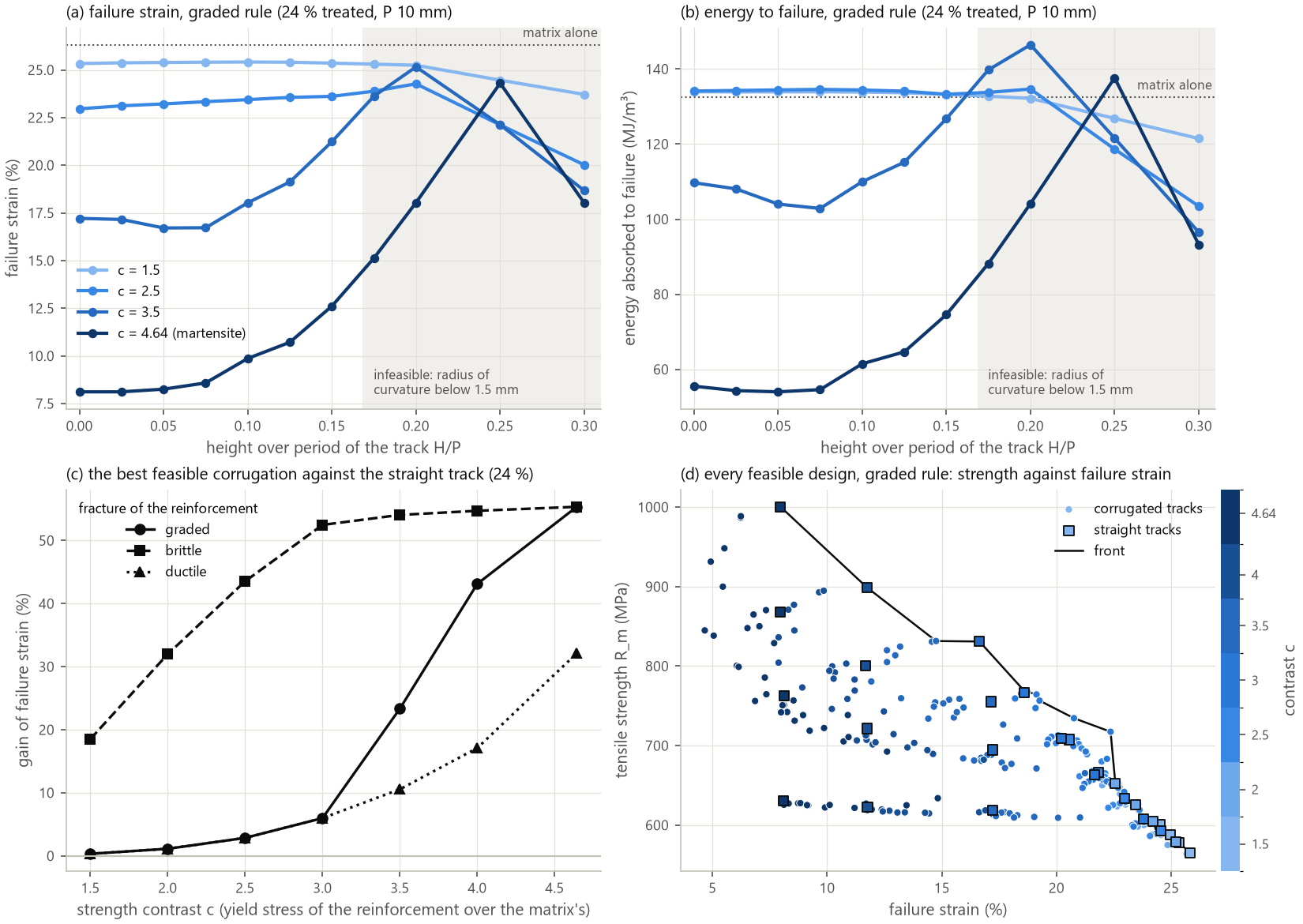
The study runs 1450 designs (seven contrasts, four fractions, H/P from 0 to 0.3 at
P = 10 mm and to 0.15 at 15 mm, three rules) on elements of 0.5 mm. At 24 % and
P = 10 mm, the straight track and the corrugation at the process limit (H/P =
0.15), R_m (MPa) / failure strain (%) / energy (MJ/m³), and the gain of failure strain
of the best feasible corrugation under each rule:
|
straight, graded |
|
gain, graded |
brittle |
ductile |
|---|---|---|---|---|---|
1.5 |
578 / 25.3 / 134 |
575 / 25.4 / 133 |
+0 % |
+19 % |
+0 % |
2 |
605 / 24.2 / 134 |
597 / 24.4 / 133 |
+1 % |
+32 % |
+1 % |
2.5 |
633 / 23.0 / 134 |
619 / 23.6 / 133 |
+3 % |
+44 % |
+3 % |
3 |
664 / 21.7 / 133 |
642 / 22.9 / 134 |
+6 % |
+52 % |
+6 % |
3.5 |
695 / 17.2 / 110 |
665 / 21.2 / 127 |
+23 % |
+54 % |
+11 % |
4 |
721 / 11.8 / 77 |
682 / 16.8 / 100 |
+43 % |
+55 % |
+17 % |
4.64 (martensite) |
763 / 8.1 / 56 |
693 / 12.6 / 75 |
+55 % |
+55 % |
+32 % |
The matrix alone reaches 553 MPa, 26.3 % and 133 MJ/m³; the reinforcement alone
(graded) 655 MPa and 22.7 % at c = 1.5, 1015 MPa and 13.7 % at 3, 1558 MPa and 6.7 %
at 4.64. Five findings:
Below a contrast of about 3 the corrugation does nothing, unless the reinforcement is brittle. A reinforcement that flows with the matrix (the graded rule below 3, where it does not reach its critical strain, and the ductile bound) gains 0 to 6 % of failure strain at the process limit and loses up to 3 % of strength: too soft to stay nearly elastic while the matrix flows, the condition of the geometric hardening (Fraser et al. 2020). The hardened AISI 430 of the thesis (
cfrom 1.4 to 1.6, a ductile track) sits there: its corrugations gave nothing. In this family a softer state also hardens more; the carburized 430 of §4, whose track hardens little (A_g10 %), gains from its corrugation.Above it, the gain grows with the contrast and with the brittleness of the reinforcement: graded, +23 % at
c= 3.5, +43 % at 4, +55 % at the martensite (8.1 to 12.6 %,R_m−9 %). A brittle reinforcement gains from 19 % atc= 1.5 to 55 %: the corrugation strains it less than the matrix (the DIC of Wang et al.), which pays at any contrast; a ductile one gains from the geometric hardening alone, 32 % at most. The ranking holds on elements of 0.25 mm (24 %,P= 10 mm,H/Pup to 0.15): the failure strains move by 1.9 points at most, the gains of the graded and brittle rules by 5 points at most; the ductile bound, whose failure is the necking alone, gains less there (+22 % instead of +32 % at the martensite: the strains of necking depend on the mesh, §4).The process limits bind. Every best feasible corrugation lies on the limit (
H/P= 0.15 atP= 10 mm, the point of the grid below 0.169), and the failure strain rises further beyond it (the martensite: 18.0 % atH/P= 0.2, a radius of 1.27 mm, 24.3 % at 0.25). The longer period does not help in this gauge: its track leaves the 5 mm before its curvature limits it. A smaller heated width (tighter curves) or a wider specimen would open the rest of the maps.The fraction acts in opposite ways on brittle and ductile reinforcements. With the martensite (graded), the best feasible corrugation gains 83 % at 12 % (
P= 15 mm,H/P= 0.15) at no cost of strength, 55 % at 24 %, 16 % at 36 %, and loses 8 % at 48 %: a wide brittle track cracks at its edges (above). A ductile reinforcement of the same contrast gains 9, 32, 66 and 75 %: more reinforcement to unbend.The energy, and the contrast as a lever of its own. The matrix alone absorbs 133 MJ/m³ up to its necking (its law of exponent 0.24): only reinforcements that do not break before the sheet necks absorb more. Within the limits the most energy goes to a reinforcement of intermediate contrast: graded,
c= 3, 48 %,P= 10 mm,H/P= 0.15, 146 MJ/m³ (+10 % over the matrix, +11 % over the reinforcement alone) atR_m= 717 MPa (+30 % over the matrix); the ductile bound reaches 165 MJ/m³ (c= 4.64, 36 %), the martensite 81 MJ/m³ at most (12 %). On the front of strength and failure strain (figure, d), straight tracks of rising contrast lie on either side of a corrugated knee (c= 3, 48 %,H/P= 0.15): at equal strength a straight track of a softer reinforcement fails later than a corrugated martensite (graded, 24 %: straight atc= 3.5, 695 MPa and 17.2 %, against the martensite atH/P= 0.15, 693 MPa and 12.6 %). Tempering the track competes with corrugating it when a softer state is tougher (the graded rule); under the brittle bound the corrugated martensite wins (7.9 % for the straight track atc= 3.5). The toughness of the states between the matrix and the martensite decides, and is to be measured.
6. Cellular design: the loop of SCOLASTIC¶
SCOLASTIC planned the patterns as the output of a loop: a cellular-automaton generator
on a grid of 1 mm cells (the laser increment, a volume that carries a homogenized
behaviour), finite elements of the load case, a local rule of the BESO type with
multigrid acceleration, several treatment levels. :mod:morphogen.laser.cells builds it:
Cells and phases.
CellGridover the parallel part (the end columns continue to the grips: the blank is treated before the specimen is cut);Phase: a flow law, a critical strain, a cost (0 untreated, 1 treated; the levels of a multi-level treatment between); a design is an array of phases, or of densities for two phases.CellProblemevaluates it (the tensile test with the fracture of §5) for an objective (energyto failure,ductility,tensile_strength,strength_ductility) under constraints on the others.Sensitivities by replay. A test records the deformation gradients of the Gauss points;
replayintegrates them again with another law: the work and plastic strains each element would have had in another phase, the kinematics held (it returns the external work within 3·10⁻⁵ with the same laws). A cell switched changes the force by the derivative of its replayed work; it breaks where its own replayed strain (with its neighbours’) reaches the critical one; the weakest cross-section of cells caps the strength (a gap in a track necks there). These estimates of every move cost a few tenths of a second.Automata.
besowithmoves="swap": the BESO rule (benefits filtered and averaged over iterations, phases chosen by a Lagrange multiplier on the budget, levels of a multi-level treatment changing one at a time; Huang & Xie 2007, 2010), each new design at the budget tested by finite elements and refused, halved, then frozen if it lowers the value.moves="exchange": the phases of two neighbouring groups of cells exchanged — a track that bends or shifts at a constant budget (a Kawasaki rule) — the best estimates tested. Cells change by orbits of a symmetry and of the period of the pattern;min_widthkeeps the designs a spot of that many cells draws (treatable);multigridsolves coarser cells first (Abdalla, Kim & Gürdal 2004; Zakhama et al. 2009).
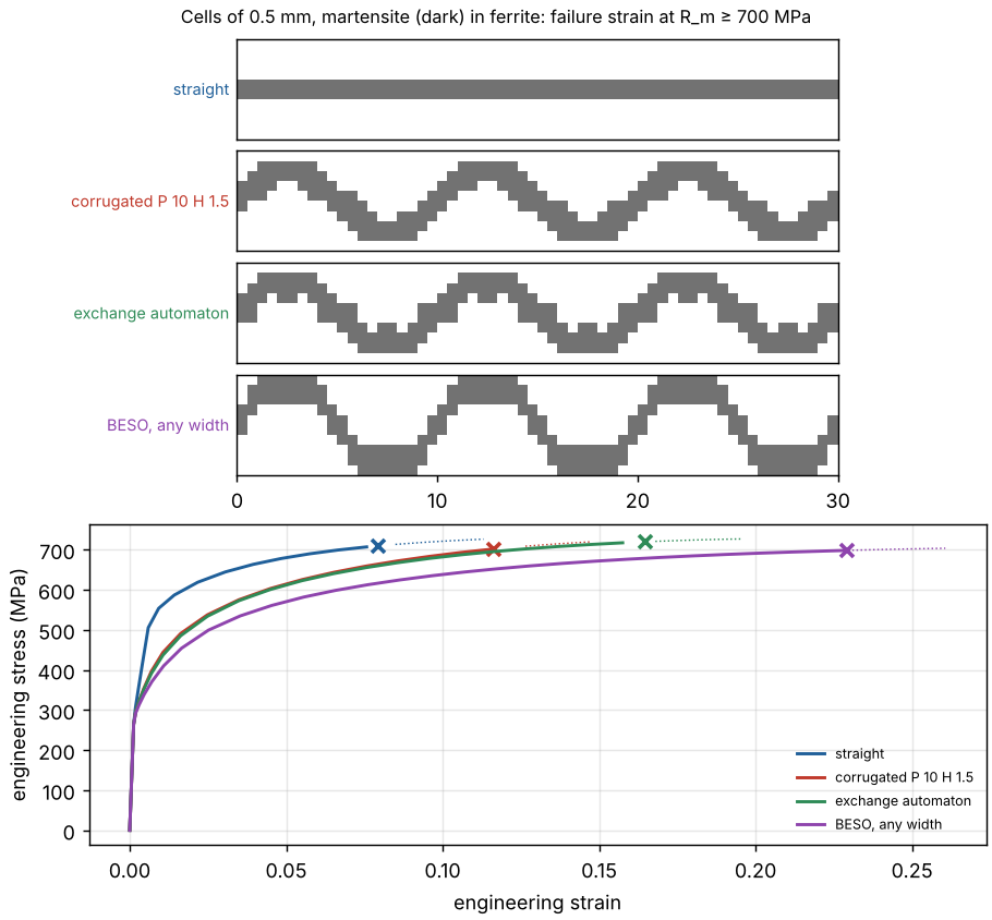
What the automata found, on cells of 0.5 mm, the phases of §5, at a constant treated
share, for the failure strain with R_m ≥ 700 MPa (examples/laser_cells.py, §3):
start, rule |
tests |
|
failure |
|
|---|---|---|---|---|
straight track, 1 mm (20 %) |
709 |
0.079 |
||
corrugated track P 10 H 1.5 drawn by a 1 mm spot (30 %) |
705 |
0.120 |
||
its exchange automaton, treatable, periodic |
41 |
719 |
0.165 |
flanks straightened, crests hollowed |
its BESO rule, treatable |
4 |
700 |
0.152 |
|
its BESO rule, any width |
18 |
698 |
0.229 |
thin steep flanks, heavy crests |
exchange automaton from the straight track |
1 |
709 |
0.079 |
nothing to gain |
exchange automaton, any width (a first try: from P 10 H 1.5 rasterized at 20 %, for |
133 |
638 |
0.228 |
islands, corner contacts |
Four findings shape the method:
The straight track is stationary. Every local move of it is estimated neutral (the strain field is uniform) and is worse when tested (a kink is a notch); the benefit of corrugation is a threshold in
H/P(§5, and the paper). Neither an automaton nor a gradient leaves it: the loop starts from a corrugation (or from a global search over its parameters,optimize).The pattern is periodic. A periodic track fails at its weakest period: a cell improved in one period moves the failure to the next. Cells change by orbits of the period and of the half-turn.
The spot sets a minimum width. Without it the automaton breaks the track into islands and corner contacts that carry no load (and cannot be drawn): the strength falls to that of the matrix (638 MPa) while the failure strain rises.
The replays rank, the finite elements decide. The replays hold the kinematics: they miss the redistribution of strain that a protrusion or a gap causes (a cell added beside a track is estimated +0.5 MJ/m³ and is −2.3). Testing the best few moves keeps only the true gains.
The best treatable design keeps the strength of the corrugated track and gains 37 % of failure strain; the unconstrained one (BESO, 0.229 at 698 MPa) points further: thin, steep flanks that unbend easily and carry little strain, heavy crests along the load that carry the strength — a track whose width varies along its path, which the power or the speed of the beam can modulate.
Tracks of variable width. The idea checked on its own (smooth tracks, the width varying linearly with the slope from the crests to the flanks, the same treated area, elements of 0.25 mm, 24 % as in the paper):
track |
crest / flank width (mm) |
|
failure |
energy (MJ/m³) |
|---|---|---|---|---|
P 10, H 1.5 (sample 6) |
1.00 / 1.00 |
685 |
0.125 |
72 |
1.30 / 0.90 |
704 |
0.141 |
84 |
|
1.40 / 0.80 |
713 |
0.169 |
104 |
|
1.50 / 0.70 |
702 |
0.169 |
103 |
|
1.80 / 0.50 |
665 |
0.136 |
78 |
|
P 15, H 1.5 (sample 4) |
1.10 / 1.10 |
733 |
0.104 |
63 |
1.40 / 0.90 |
730 |
0.113 |
70 |
|
1.60 / 0.75 |
694 |
0.092 |
54 |
At H/P = 0.15, crests 40 % wider than the flanks gain 4 % of strength and 35 % of
failure strain together, the energy to failure 44 %; flanks thinner than about 0.7 mm
lose it again, and the gentler corrugation (0.1) gains little. A beam slowed down or
strengthened at the crests draws such a track; the process model’s cycles are those of
a constant beam, so that the realized widths remain to be computed along the path.
7. Topology optimization by densities¶
hca (the hybrid cellular automaton of Tovar et al. 2006: each cell’s stimulus,
averaged over its neighbourhood, drives its density towards the set point of the
budget) and topology (SIMP-like mixing of the flow stresses by x^q, density filter,
Heaviside projection, MMA; Bendsøe 1989; Amir 2017 for two plastic phases) take the
derivatives of the value from replays at x ± 0.05. From the same corrugated start
they return it (R_m 701 MPa, failure 0.116 and 0.114): derivatives at fixed kinematics
see the strength a cell adds, not the strain it moves onto the martensite next to it.
The redistribution needs the adjoint of the path-dependent problem (Michaleris,
Tortorelli & Vidal 1994; Alberdi et al. 2018), a storage of every state and a backward
solve per step — not implemented; the tested automaton of §6 replaces it. (The voxel
topology optimization of morphogen.optimization — OC, MMA, BESO, HCA — is the
linear-elastic counterpart for periodic cells with voids; here both phases are solid,
have the same Young’s modulus, and only plasticity and fracture differ, so that
compliance sensitivities vanish.)
8. From cells to laser paths¶
design_tracks turns a design into the centre lines of its tracks (the midpoints of the
runs of treated cells of each column, linked across columns; cross=True crosses the
runs longer than the spot end to end, so that a square spot covers every cell — a real
track, wider than the spot, then treats too much: 44 % instead of 34 % below),
CellGrid.stamp draws polylines with a spot; a SheetCase with the pattern
{"kind": "polylines", "tracks": ...} treats them with the process model (fibre and
diode beams, metallurgy of the annealed MS1500). Every design above is one continuous
track:
design |
treated |
|
|
|
|---|---|---|---|---|
straight track |
0.28 |
495 |
848 |
8.3 |
corrugated P 10 H 1.5 |
0.32 |
372 |
735 |
16.4 |
exchange automaton |
0.34 |
376 |
752 |
17.2 |
The gain of the automaton survives the process (strength and elongation, the latter by
Considère: the process model has no fracture by default — its partly transformed zones
need their own critical strains, SheetMaterial.fracture, a table of hardness).
10. Other load cases: a crack, a corner, the anisotropy¶
SCOLASTIC proposed three applications beyond the tensile test: controlling the
plastic anisotropy of the sheet, forming, and steering or blunting cracks.
morphogen.laser.structures adds the structures (meshes of structured blocks
graded towards the singular points, a displacement-controlled test, the initiation of
a crack where a phase reaches its critical plastic strain, averaged within the phase
over 0.5 mm), and CellProblem takes them as cases: the
automata of §6 apply. Phases of §5 (annealed steel, martensite); the critical strain of
the ductile matrix at a crack tip, 0.5, is an assumption (about half its fracture
strain in tension), as are those of the hard sheets below.
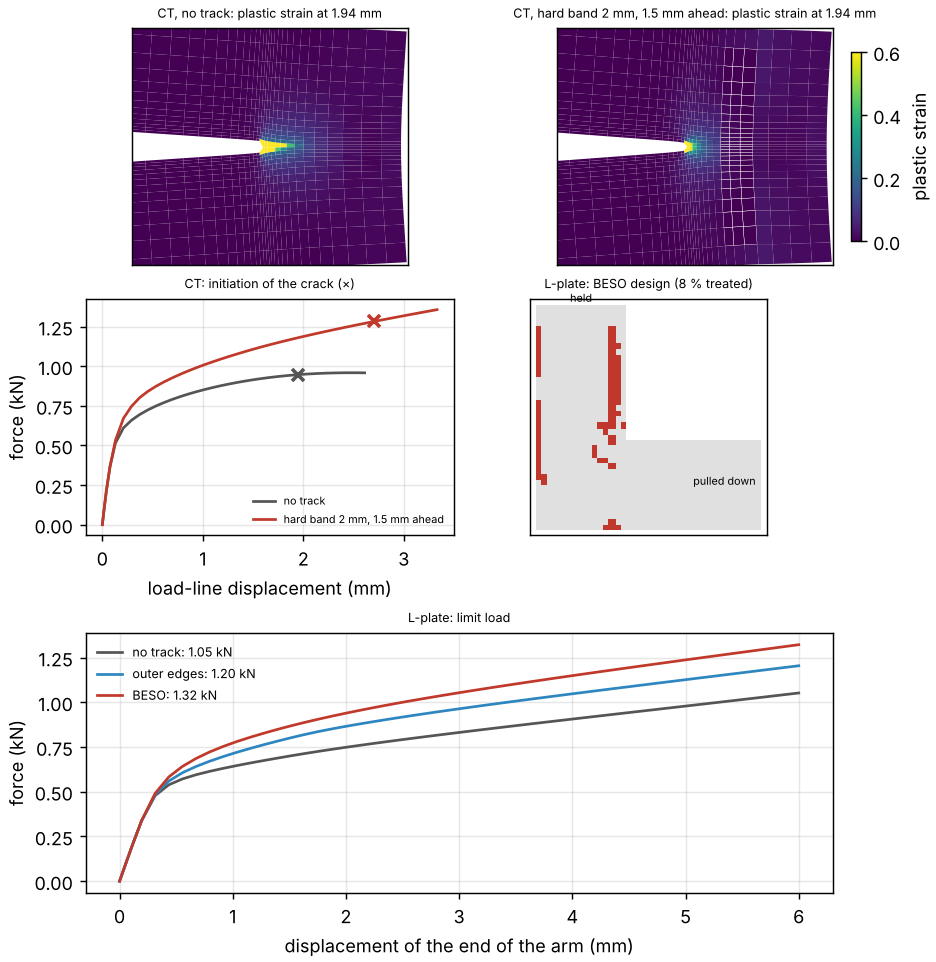
Compact tension (CompactTension: ASTM E399 proportions, W = 20 mm, a/W = 0.5,
1 mm; pins as stars of bars that turn freely — the elastic load-line compliance within
2.5 % of Saxena & Hudak 1978). The force, the load-line displacement and the work at
the initiation, the treated share of a 12 × 10 mm box around the tip:
hard tracks in the annealed steel |
treated |
force (kN) |
displacement (mm) |
energy (J) |
initiation |
|---|---|---|---|---|---|
none |
0 |
0.95 |
1.94 |
1.54 |
tip, matrix |
band 1 mm across the crack path, 1 mm ahead |
0.12 |
1.27 |
2.23 |
2.27 |
the band breaks |
band 2 mm, 1.5 mm ahead |
0.12 |
1.28 |
2.70 |
2.76 |
tip |
band 1 mm, 2 mm ahead |
0.08 |
1.19 |
2.51 |
2.39 |
tip |
band 1 mm, 4 mm ahead |
0.04 |
0.99 |
2.02 |
1.65 |
tip |
short barrier (` |
y |
< 2.5 mm`), 2 mm ahead |
0.06 |
1.12 |
2.40 |
bands along the crack, |
0.36 |
0.96 |
1.57 |
1.27 |
tip |
A hard band across the path of the crack, ahead of its tip, shields it: the tip of the matrix initiates later, at a 36 % higher force and with 79 % more energy for a band of 2 mm at 1.5 mm; closer or thinner, the band breaks first; it must cross the whole plastic zone (a short barrier does less), and bands along the crack confine the plasticity and lower the energy. The ranking does not hang on the assumed critical strain of the matrix: at 1.0 (a tougher matrix; the critical strain of ductile initiation depends on the triaxiality and the Lode angle, Neimitz et al. 2018), the untreated specimen initiates at 0.96 kN and 2.02 J, the band of 2 mm at 1.5 mm at 1.40 kN and 4.18 J (+107 %), the band of 1 mm at 2 mm with +87 %, the bands along the crack with −36 %. In hard sheets softened by the laser the rules turn over (the configurational forces of a crack meeting a change of yield strength: Simha et al. 2005; Kolednik et al. 2011; Sistaninia & Kolednik 2014 — a crack running into a harder region is shielded, into a softer one anti-shielded):
hard sheet, softened bands |
force (kN) |
displacement (mm) |
energy (J) |
|---|---|---|---|
DP1180 (critical 0.25), none |
1.85 |
0.77 |
1.03 |
tempered band 1.5 mm around the tip (0.40) |
1.82 |
0.82 |
1.07 |
tempered band 1.5 mm, 2 mm ahead |
1.73 |
0.74 |
0.94 |
tempered bands along the crack, |
1.79 |
0.95 |
1.28 |
AA6082-T6 (critical 0.20), none |
0.55 |
0.64 |
0.25 |
softened band around the tip (60 HV, 0.35) |
0.55 |
1.00 |
0.41 |
softened band, 2 mm ahead |
0.50 |
0.63 |
0.22 |
softened bands along the crack |
0.46 |
0.95 |
0.33 |
A soft band ahead of the tip draws the crack (anti-shielding); the tip inside a soft band, or soft bands beside the crack that take the plasticity (the “relief zones” of Kahrimanidis et al. 2015 for forming), raise the energy of initiation at nearly the same force: by 24 % in the DP1180 with bands beside the crack, by 66 % in the AA6082-T6 with its tip in a softened band. The rules of thumb: hard ahead of a soft tip, soft around a hard tip, never soft ahead. The automata of §6 (1 mm cells) found no local improvement of the hard band at 2 mm: a local optimum. From an untreated sheet, the BESO rule (the budget raised to 10 % by 1 % per iteration, 34 tests) builds a chevron of hard cells 2 to 5 mm ahead of the tip: +15 % of energy, a poorer optimum than the straight band placed by hand (+55 % at 8 %) — the automaton refines, the designer’s rule starts it. So far the initiation; the growth of the crack follows.
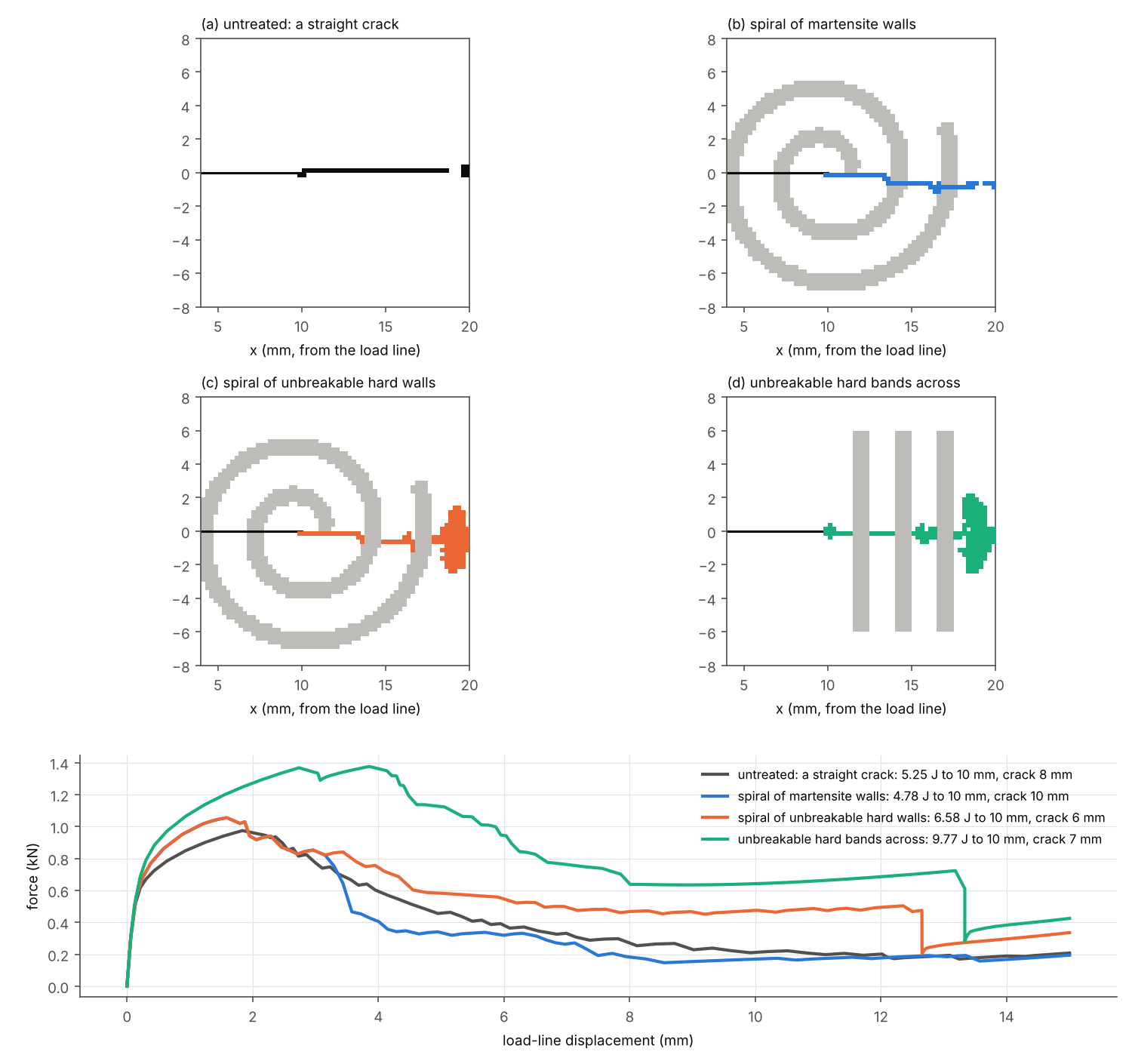
Guiding the crack (SCOLASTIC: a spiral path, longer than a straight one, spending
more energy). The crack now grows (CompactTension(propagate=True); theory: an element
breaks when the averaged plastic strain of its phase reaches the critical one, the
specimen is rebalanced at the same displacement — unstable growth as it comes — on a box
of uniform elements of 0.25 mm over the ligament). The annealed steel (critical strain
0.5 at a crack tip), a spiral about the tip (pitch 3 mm, walls 1 mm wide, two turns:
20 % of the box), or three straight bands 1 mm wide across the ligament (12 % of the box);
the work and the length of the crack at a load-line displacement of 10 mm, the work at
15 mm:
tracks |
work to 10 mm (J) |
crack at 10 mm (mm) |
work to 15 mm (J) |
|---|---|---|---|
none: a straight crack |
5.25 |
7.8 |
6.22 |
spiral of martensite walls (critical 0.075) |
4.78 |
9.5 |
5.66 |
the same, pitch 4 mm, walls 1.5 mm |
4.41 |
9.8 |
4.89 (separated at 12.7 mm) |
spiral track of martensite 0.5 mm wide (a brittle path) |
4.78 |
9.3 |
5.72 |
spiral of hard walls, critical 0.2 |
5.57 |
7.8 |
6.60 |
the same, critical 0.5 |
6.16 |
7.0 |
7.69 |
the same, unbreakable |
6.58 |
6.0 |
8.54 |
straight bands across, martensite |
5.90 |
11.5 |
6.90 |
the same, critical 0.2 |
7.68 |
8.5 |
9.03 |
the same, critical 0.5 |
8.70 |
7.5 |
10.46 |
the same, unbreakable |
9.77 |
7.0 |
12.67 |
The opening of a CT specimen does not let the crack turn: it keeps the straight line of mode I, cuts brittle walls (the martensite breaks at 7.5 %: less work than without tracks) and, when the walls hold, starts again in the matrix behind each of them — the walls left as bridges across the crack, holding its faces together (figure: the force after the crack has passed, twice that of the untreated specimen). The spiral works as a set of bridges, not as a path (+25 % of work to 10 mm with unbreakable walls); straight bands across the ligament, their whole length across the opening, bridge better (+86 %, the maximum force +42 %). The gain follows the toughness of the tracks: bands that break at a plastic strain of 0.2 (a tempered or low-carbon martensite) give +46 %, at 0.5 +66 %, the brittle martensite of the annealed MS1500 +12 %: hard tracks that do not break, rather than a longer path, are what spends the energy. To steer the crack along a curve the walls would have to hold the opening over the whole corridor: a curvature much gentler than a spiral of a few millimetres, or a loading in mixed mode. Limits: the elements break one by one (a crack one element wide, the averaging radius of 0.5 mm), a membrane (no shear lips, nothing out of the plane), critical strains assumed.
L-shaped plate (LPlate: 40 mm, arms 16 mm, 1 mm, held along its top edge, the
end of its arm pulled down 6 mm; the largest force up to there — the strength, the
force still rising slowly as the matrix hardens):
hard tracks |
treated |
force at 6 mm (kN) |
|
|---|---|---|---|
none |
0 |
1.05 |
|
outer edges |
0.08 |
1.20 to 1.24 |
no fracture |
inner edges, through the re-entrant corner |
0.05 |
1.10 |
the martensite breaks at the corner at 2 to 3 mm |
block of 8 mm around the corner |
0.05 |
1.13 |
|
BESO from the outer edges |
0.08 |
1.32 |
flanges of the vertical arm, 2–3 mm off the corner |
Hardening raises the limit load by a quarter with 8 % of the plate treated when the martensite stays away from the stress concentration: the brittle phase at the corner breaks first. (The automaton is kept off the held and pulled edges, whose uniform displacements it otherwise reinforces.)
Plastic anisotropy (SCOLASTIC’s first application). With directions=(0, 45, 90)
the tensile tests give, besides the yield and tensile strengths, Lankford’s coefficient
r of each direction (the width strain over the thickness strain at 10 % or before
necking: 1.000 for the untreated sheet, isotropic von Mises), the normal and planar
anisotropies r̄ = (r0 + 2 r45 + r90)/4, Δr = (r0 − 2 r45 + r90)/2 and Hill’s 1948
coefficients from the r values (hill48; F, G, H, N = 0.5, 0.5, 0.5, 1.5 when
isotropic); the objectives isotropy (of the yield strength) and flow_isotropy (of
r). On the specimens of the thesis, 5 mm wide, a pattern of a few millimetres is a
structure: their r depends on how many tracks the gauge holds and where. The
anisotropy of the sheet is that of its periodic cell (loading={"kind": "cell"}:
morphogen.laser.periodic, the lattice of the pattern, the macroscopic gradient among
the unknowns, a uniaxial stress in any direction; checked against Hill’s r(α), the
rule of mixtures of a laminate and the curve of the untreated sheet). Annealed MS1500,
martensitic tracks:
pattern |
treated |
|
|
|
|
|
spread of |
|---|---|---|---|---|---|---|---|
one family along 0°, 2.5 mm apart |
0.53 |
1.00 / 0.95 / 0.15 |
1.00 / 1.58 / 0.04 |
1.05 |
−1.06 |
783 / 357 / 395 |
0.83 |
crossed ±30°, 5 mm |
0.46 |
1.06 / 0.77 / 0.33 |
1.25 / 0.39 / 0.56 |
0.65 |
+0.52 |
506 / 500 / 367 |
0.30 |
crossed ±45°, 5 mm |
0.46 |
0.69 / 0.72 / 0.68 |
1.85 / 0.28 / 1.85 |
1.07 |
+1.57 |
377 / 522 / 377 |
0.34 |
honeycomb, side 3 mm |
0.45 |
0.96 / 0.80 / 0.57 |
0.79 / 0.95 / 0.85 |
0.89 |
−0.13 |
450 / 442 / 430 |
0.05 |
The tracks set the anisotropy of the sheet over a wide range, by their structure: a
family holds the width of the sheet pulled across it (r90 = 0.04: the soft layers
between the tracks in plane strain) and lets it shear along them at 45° (r45 = 1.58:
a shear does not thin the sheet); crossed families do the same about their bisectors
(at ±45°, r0 = r90 = 1.85 and r45 = 0.28); the honeycomb is nearly isotropic, in
yield (within 5 %) and in r (0.79 to 0.95). The narrow specimens tell otherwise —
the crossed tracks at ±45° looked isotropic on them (Δr = −0.03), the tracks across
them seemed to restrain the width less: the anisotropy of an architectured sheet is
computed on its cell, or measured on specimens many periods wide. (The isotropic yield
strengths optimized on specimens in the first version of this study, crossed tracks
within 8 to 11 %, are the specimens’.)
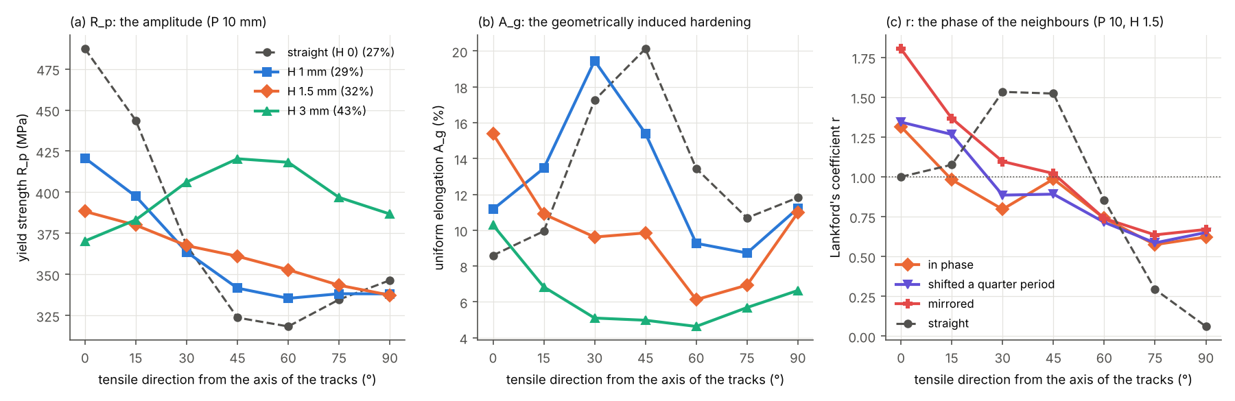
The anisotropy of an architecture. Wang et al. (2023) pulled their corrugated tracks along their axis; the cell pulls them in every direction. Sine tracks along x, 5 mm apart (period P, height H), on an isotropic sheet (the annealed MS1500), every 15° (figure): the architecture alone sets the anisotropy, continuously. Straight tracks (27
their corrugation lowers the first and raises the second: at H = 1.5 mm the yield
strength falls evenly from 388 to 337 MPa, at H = 2 mm it stays within ±6 % in every
direction (345 to 386 MPa), at H = 3 mm the anisotropy has turned over (strongest at
45°, 420 MPa, weakest along the tracks, 370 MPa); shorter periods even it at a smaller
height (P = 5 mm, H = 1.5 mm: 383 to 411 MPa, 43 % treated). Along the tracks the
corrugation raises the uniform elongation from 8.6 % (straight) to 15.4 % (H = 1.5 mm):
the geometrically induced work hardening of Wang et al. 2023, the tracks straightening
as the sheet stretches — paid off the axis (6.1 % at 60°). Lankford’s coefficient
follows the phase of the neighbours as much as the shape of a track: in phase, r0 =
1.31; shifted by a quarter period, 1.34; mirrored (the tracks closing into cells), r0
= 1.80 for r90 = 0.67 — a normal anisotropy out of an isotropic steel, as a texture
would give it. The architecture is a texture that can be drawn; the next paragraphs use
it against a rolling texture.
A rolled sheet, compensated (the aim: start from a sheet with a rolling
texture and treat it to compensate its plastic anisotropy). A cold-rolled and annealed
low-carbon steel has the γ fibre ({111} planes in the sheet) and Lankford coefficients
of the order of r0 = 1.6, r45 = 1.2, r90 = 2.0 (Ray, Jonas & Hook 1994): r̄ =
1.5, good for deep drawing, and Δr = +0.6, four ears at 0° and 90° in a drawn cup.
SheetMaterial.anisotropy gives them to the untreated steel through Hill’s 1948
criterion in plane stress, fitted to them (theory: the return mapping, its tangent, the
axes of the texture turning with the material). A track transforms the steel; its
martensite forms from austenite with a weak texture, isotropic here, or inherits a share
memory of the sheet’s (the texture of a fast-heated steel survives its double
transformation in part: Ray & Jonas 1990; Petrov, Sidor & Kestens 2012 above 1000 °C/s,
the heating rates of a laser track). The texture given to the annealed MS1500, on the
cell of the sheet (elements of 0.25 mm, 0.125 mm for the walls of the honeycombs; r at
10 % or 0.8 A_g; the spread of r, max − min over the mean, at 0°/45°/90°):
rolled sheet, treated by |
treated |
|
|
|
spread of |
|
|
|---|---|---|---|---|---|---|---|
nothing |
0 |
1.59 / 1.20 / 1.97 |
1.49 |
+0.58 |
0.49 |
294 / 345 / 308 |
16.6 |
tracks along RD, 5.6 mm apart |
0.24 |
1.41 / 1.67 / 0.40 |
1.29 |
−0.77 |
1.09 |
461 / 373 / 376 |
8.9 |
tracks along RD, 10 mm |
0.13 |
1.49 / 1.60 / 0.91 |
1.40 |
−0.40 |
0.51 |
376 / 359 / 344 |
11.4 |
tracks along RD, 14 mm |
0.09 |
1.52 / 1.50 / 1.15 |
1.42 |
−0.17 |
0.26 |
350 / 354 / 334 |
12.6 |
tracks along RD, 20 mm |
0.07 |
1.54 / 1.41 / 1.36 |
1.43 |
+0.04 |
0.13 |
332 / 351 / 326 |
13.7 |
tracks along RD, 28 mm |
0.05 |
1.55 / 1.35 / 1.51 |
1.44 |
+0.19 |
0.14 |
320 / 349 / 321 |
14.4 |
tracks along TD, 10 mm |
0.13 |
0.81 / 1.46 / 1.79 |
1.38 |
−0.16 |
0.72 |
326 / 357 / 391 |
11.5 |
square grid along RD and TD, 10 mm |
0.25 |
0.90 / 1.80 / 1.12 |
1.40 |
−0.79 |
0.71 |
406 / 376 / 430 |
8.1 |
square grid turned 45°, 10 mm |
0.25 |
2.33 / 0.68 / 2.97 |
1.66 |
+1.97 |
1.15 |
320 / 456 / 334 |
5.9 |
grid: along RD every 24 mm, along TD every 39 mm (optimized, below) |
0.09 |
1.34 / 1.43 / 1.45 |
1.41 |
−0.04 |
0.08 |
333 / 354 / 342 |
12.0 |
honeycomb, two sides along RD, side 5 mm |
0.28 |
1.36 / 1.39 / 1.60 |
1.43 |
+0.09 |
0.17 |
360 / 411 / 373 |
6.4 |
honeycomb, side 4 mm |
0.35 |
1.33 / 1.20 / 1.43 |
1.29 |
+0.18 |
0.18 |
386 / 437 / 396 |
5.2 |
honeycomb, side 3 mm |
0.45 |
1.16 / 1.07 / 1.20 |
1.12 |
+0.11 |
0.12 |
444 / 492 / 445 |
4.2 |
The tracks act by their structure more than by the texture they erase. Along the rolling
direction, they hold the width of the sheet pulled across them (r90 falls: the steel
between them in plane strain) and let it shear along them at 45° (r45 rises: a shear
does not thin the sheet) — both lower Δr, as a γ-fibre steel needs; sparse, they yield
in compression and hold less. One track every 20 mm, 7 % of the sheet, brings Δr from
+0.58 to +0.04 and the spread of r at 0°/45°/90° from 0.49 to 0.13, keeps r̄ (1.43)
and most of the ductility (A_g 13.7 %), and evens the yield strength (spread 0.08
instead of 0.16). The same tracks along the transverse direction lower r0 instead (the
wrong way here), a square grid along RD and TD raises r45 too much, the same grid
turned 45° triples Δr (+1.97): the orientation of the pattern on the texture decides.
A honeycomb with two sides along RD adds the isotropy of its network to the erasing of
the texture: at 0°/45°/90°, r within ±6 % with 45 % of the sheet treated, Δr = +0.09
with 28 % (keeping r̄ = 1.43). Had the tracks kept the texture (memory = 1), those
along RD would compensate as well (14 mm: Δr −0.14 instead of −0.17), the honeycomb of
3.5 mm less (spread 0.16 instead of 0.09): the structure first, the erased texture
second.
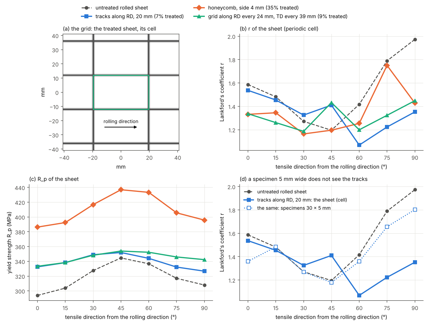
The whole profile. Three directions are not the sheet (figure): over 0° to 90° every
15° (directions=range(0, 91, 15)), the untreated sheet spreads r over 0.51 (from
1.20 at 45° to 1.97 at 90°). The tracks along RD 20 mm apart bring it to 0.35 only: they
compensate Δr, not the profile — they hold the width of the sheet from 60° on (r =
1.07 at 60°), where the texture raises r from 75° on. The honeycombs, nearly isotropic
at 0°, 45° and 90°, peak at 75° (r = 1.56 to 1.96; a network of period 60° has not the
harmonics of the texture): 0.43 to 0.50. A second family along TD, sparser, lowers r0
too and flattens the profile further: the Bayesian optimization of the two spacings over
the whole profile (at most 25 % treated; cells of 0.5 mm, 18 evaluations) finds tracks
along RD every 24 mm and along TD every 39 mm — 9 % of the sheet, r from 1.19 to 1.45
over 0°–90° (spread 0.20 instead of 0.51, on cells of 0.25 mm; 0.08 at 0°/45°/90°), Δr
= −0.04, r̄ = 1.41, the yield strength within 6 % (333 to 354 MPa). The tracks along
RD alone, as sparse, leave 0.28 to 0.31 (25 to 35 mm apart). A specimen 5 mm wide hardly
sees the tracks along RD (figure, d): r90 = 1.80 against 1.35 for the sheet.
The price of the compensation is small for the sparse tracks: a few per cent of the
sheet treated, r̄ kept near 1.4 (the drawability of the γ fibre), the yield strength
up by 5 to 15 % and evened, the uniform elongation down from 16.6 % to 12 to 14 % along
the axes — 6.3 % at 30° for the grid, where its cells localize the strain. Hill’s
quadratic criterion, fitted to the r values, ties the anisotropy of the yield
strength to them (the untreated sheet 15 % stronger at 45°): the yield strengths need a
criterion of their own (below).
Yld2000-2d: the yield strengths too. Fitted to the r values, Hill’s criterion sets
the yield anisotropy for them; a rolled sheet has its own. A DC04 (Banabic & Sester
2012): σ = 151, 166, 163 MPa at 0°, 45°, 90° and 192 MPa in equibiaxial tension, r =
1.83, 1.39, 2.11 (rb = 0.87, Hill’s r0/r90, not measured); Barlat’s Yld2000-2d
(anisotropy={"criterion": "yld2000", ...}, exponent 6) fitted exactly to the eight
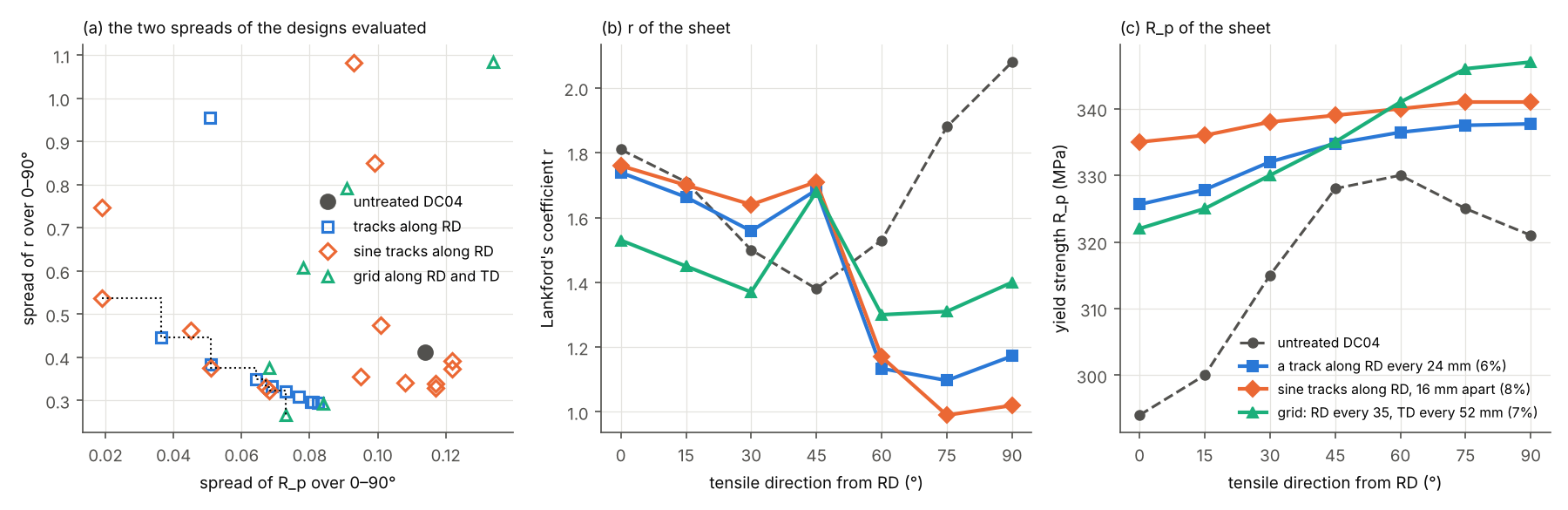
(theory). Its texture given to the annealed MS1500, on the cell: r from 1.38 (45°) to
2.08 (90°), R_p from 294 (0°) to 330 MPa (60°) — spreads of 0.41 and 0.115 over 0°–90°
every 15°. The tracks along RD strengthen the sheet most along them, where the DC04 is
weakest: they even R_p (one track every 24 mm: spread 0.036; sine tracks 16 mm apart,
P = 20 mm, H = 1 mm: 0.019, within ±1 %) — and in the same gesture hold the width of the
sheet pulled across them, r falling at 60°–90° below its value at 45°: the spread of
r grows again (0.45, 0.54). The two anisotropies of this texture are not compensated
by one gesture. The designs evaluated by Bayesian optimization (tracks along RD, sine
tracks along RD, grids along RD and TD; cells of 0.5 mm, both profiles over 0°–90°, at
most 25 % treated) make a front (figure, a): sparse patterns lower both spreads together
— a grid along RD every 35 mm and along TD every 52 mm, 7 % of the sheet: 0.27 and 0.073
(−35 % and −37 %), r̄ = 1.57 —; denser ones even R_p at the cost of r. With Hill’s
criterion the yield anisotropy followed the r values and fell with them; with the
yield stresses of the DC04, the structure that compensates the one works against the
other. (Yld2000-2d at 0.25 mm: r within 2 % and σ within 0.7 % of the criterion in
the cell, two Newton iterations a step.)
The sheet in its volume (morphogen.laser.solid,
theory). The membrane is in plane
stress, layer by layer. case_volume draws the periodic cell of the treated sheet as a
voxel image for the solvers of three-dimensional fields: the hardness that the laser path
leaves in each layer sorted into classes, each a phase with the flow law of its hardness
(as von Mises plasticity: Voce’s law exactly, the power laws fitted within 1.5 %), and a
gap of void voxels above the sheet, so that its two faces are free. The image is a
microstructure like any other: its tensile test by the nonlinear FFT solver
(volume_tension), its fields across the thickness, its other properties
(homogenize), a conforming mesh.
from morphogen.laser import SheetCase, case_volume, volume_tension

case = SheetCase(
    material="annealed_ms1500",
    element=0.25,
    loading={"kind": "cell"},
    pattern={"kind": "straight", "angle": 0.0, "count": None, "spacing": 6.0},
)
image, materials = case_volume(case)  # 8 x 24 x (4 + 2) voxels, phases by hardness
print(image.metadata["hardness"])  # {1: 167, 2: 444, 3: 504} HV
along = volume_tension(image, materials, axis=0, strain=0.03)  # along the tracks
across = volume_tension(image, materials, axis=1, strain=0.03)
print(along["stress"][-1], across["stress"][-1])  # 760 and 589 MPa
On this cell (straight tracks 6 mm apart in a sheet of 1 mm, a fifth of it martensite) the volume and the membrane agree within 1.3 % along the tracks and within 3 % across them (true stresses up to 3 % of strain; the volume is the stiffer one across the tracks, where the membrane lets each layer thin as it flows), and the widths shrink alike (0.48 and 0.16 of the strain): the plane stress of the layers is a sound assumption for these sheets. Hard and soft halves side by side or one above the other follow the mean of their two laws within 3e-4. The volume is in small strains and has no fracture criterion: it complements the membrane (fields through the thickness, stresses across the tracks, other physics on the same image), it does not replace its tensile test up to necking.
11. Alternative materials¶
sheet_material("22mnb5"): the boron steel of hot stamping as delivered (75 % ferrite,
25 % pearlite, 185 HV: R_p about 400, R_m 520 MPa, A_g 18 %) hardened by
martensitic tracks (up to 550 HV: 1150 and 1590 MPa; Karbasian & Tekkaya 2010; Merklein
et al. 2006) — the steel of the laser-patterned crash tubes of Kim & Yoon (2021).
sheet_material("aa6082_t6"): an age-hardened aluminium alloy softened by the laser
(PeakSoftening: the hardness lost as a function of the peak temperature, the largest
loss of the cycles kept — overaged near 350 to 400 °C, down to 60 HV for good;
dissolved above about 480 °C, then naturally aged back to about 80 HV; Myhr & Grong
1991; the alloy and the treatment of the tailor heat-treated blanks of Piccininni &
Palumbo 2020), with the elasticity of aluminium. Through the whole chain:
sheet, track |
|
|
|
treated |
|---|---|---|---|---|
22MnB5 1.5 mm, none |
397 |
521 |
17.5 |
0 |
straight (200 + 150 W) |
416 |
557 |
15.8 |
0.03 |
corrugated P 10 H 1.5 |
409 |
556 |
16.1 |
0.04 |
AA6082-T6 1 mm, none |
288 |
331 |
6.8 |
0 |
softened straight (2 × 260 W, 20 mm/s) |
174 |
256 |
10.7 |
0.48 |
softened corrugated P 10 H 1.5 |
125 |
223 |
12.9 |
0.53 |
The boron steel behaves as the annealed MS1500, with a thicker sheet that needs more power: the track of 200 + 150 W hardens only 3 % of 1.5 mm, to 504 HV at most. The aluminium alloy turns the logic over: the laser softens it, trading strength for ductility (as T6 for T4), and its diffusivity spreads the track: a single track of 1.5 mm softens half of the 5 mm gauge — architectures of aluminium have features of a few millimetres, not one; the soft bands ahead of or around a crack (§10) are its use. Titanium alloys (Ti-6Al-4V: α’ martensite after laser heating above the β transus, gas nitriding of the surface) and magnesium are not modelled.
12. Use¶
from morphogen.laser import Beam, SheetCase, Specimen, optimize

case = SheetCase(
    material="annealed_ms1500",
    specimen=Specimen(kind="dogbone", length=30.0, width=5.0, thickness=1.0),
    beam=Beam(power=150.0, speed=10.0, radius=0.5, absorptivity=0.55),
    bottom=Beam(power=100.0, speed=10.0, radius=0.6, absorptivity=0.55, profile="tophat"),
    configuration="symmetric",
    pattern={"kind": "corrugated", "count": 1, "amplitude": 1.0, "period": 15.0},
)
result = case.evaluate()
print(result.measures["tensile_strength"], result.measures["uniform_elongation"])

best = optimize(
    case,
    {"pattern.amplitude": [0.0, 2.5], "pattern.period": [6.0, 30.0]},
    objective="strength_ductility",
    constraints={"yield_strength": [400.0, None], "min_radius": [1.5, None]},
    method="bayesian",
    evaluations=30,
)
print(best.values, best.objective)
print(best.result.path.to_gcode())  # the laser path of the optimum
Bending and directions are options of the case: loading={"kind": "bending", "span": 30.0, "deflection": 1.0} with a Specimen(kind="strip", ...), and directions=(0, 45, 90) (the measures are then the means, yield_strength_45… each direction’s, and
yield_anisotropy, strength_anisotropy, elongation_anisotropy).
Cellular designs (§5–§8):
from morphogen.laser import CellProblem, SheetCase, beso, design_tracks, wang_phases
from morphogen.laser.cells import corrugation

problem = CellProblem(
    phases=wang_phases(),  # ferrite and brittle martensite (§5)
    size=0.5,  # cells of 0.5 mm
    objective="ductility",  # the failure strain...
    constraints={"tensile_strength": [700.0, None]},  # ...at R_m >= 700 MPa
)
start = problem.grid.stamp(corrugation(problem.specimen, 1.5, 10.0))  # a 1 mm spot
run = beso(
    problem,
    start,
    budget=None,
    moves="exchange",
    symmetry=("point",),
    period=10.0,
    min_width=2,
    candidates=6,
)
print(run.summary())
tracks = design_tracks(problem.grid, run.design)  # the laser path that draws it
case = SheetCase(pattern={"kind": "polylines", "tracks": [t.tolist() for t in tracks]})
print(case.evaluate().measures["tensile_strength"])
Structures and directions (§10):
from morphogen.laser import CellProblem, FlowLaw, SheetCase
from morphogen.laser.cells import Phase
from morphogen.laser.structures import CompactTension, LPlate

phases = (
    Phase("ferrite", FlowLaw.hollomon(280, 986, 0.24), critical=0.5, cost=0),
    Phase("martensite", FlowLaw.hollomon(1300, 1966, 0.06), critical=0.075),
)
ct = CellProblem(
    phases=phases,
    case=CompactTension(max_disp=5.0),
    size=0.25,
    fracture_radius=0.5,
    objective="energy",
)
band = ...  # an array of the cells of ct.grid (1: martensite)
print(ct.evaluate(band).measures)  # failure_strain: the initiation (load-line / W)
sheet = SheetCase(
    pattern={"kind": "crossed", "angle": 45.0, "spacing": 5.0}, directions=(0, 45, 90)
)
m = sheet.evaluate().measures
print(m["r_value_0"], m["r_bar"], m["delta_r"], m["hill_n"])
A rolled sheet and its compensation (§10), on the periodic cell of the sheet treated all over:
from dataclasses import replace
from morphogen.laser import SheetCase, sheet_material

rolled = replace(
    sheet_material("annealed_ms1500"), anisotropy={"r0": 1.6, "r45": 1.2, "r90": 2.0}
)  # + "memory": 0..1
sheet = SheetCase(
    material=rolled,
    element=0.25,
    pattern={"kind": "honeycomb", "cell": 3.0},
    loading={"kind": "cell"},  # the cell of the lattice of the pattern
    directions=(0, 45, 90),
)
m = sheet.evaluate().measures
print(m["r_value_0"], m["r_value_45"], m["r_value_90"], m["r_anisotropy"], m["r_bar"])
Yld2000-2d (yield stresses and Lankford coefficients of a DC04) and the growth of a crack (§10):
from dataclasses import replace
import numpy as np
from morphogen.laser import CellProblem, FlowLaw, SheetCase, sheet_material
from morphogen.laser.cells import Phase
from morphogen.laser.structures import CompactTension

dc04 = {
    "criterion": "yld2000",
    "s0": 151,
    "s45": 166,
    "s90": 163,
    "sb": 192,
    "r0": 1.83,
    "r45": 1.39,
    "r90": 2.11,
    "rb": 0.87,
    "a": 6,
}
rolled = replace(sheet_material("annealed_ms1500"), anisotropy=dc04)
sheet = SheetCase(
    material=rolled,
    element=0.25,
    loading={"kind": "cell"},
    pattern={"kind": "straight", "angle": 0.0, "count": None, "spacing": 60.0},
    directions=tuple(range(0, 91, 15)),
)
print(sheet.evaluate().measures["yield_anisotropy"])

ct = CompactTension(
    max_disp=15.0, fine=0.25, refine=(4.0, 20.0, 9.0), propagate=True, region=(4.0, 20.0, -9.0, 9.0)
)
phases = (
    Phase("ferrite", FlowLaw.hollomon(280, 986, 0.24), critical=0.5, cost=0),
    Phase("hard wall", FlowLaw.hollomon(1300, 1966, 0.06), critical=float("inf")),
)
problem = CellProblem(phases=phases, case=ct, size=0.25, fracture_radius=0.5)
walls = ...  # an array of the cells of problem.grid (1: hard), e.g. along a spiral
result = problem.evaluate(walls).result
broken, at = result.fields["broken"]  # the elements of the crack, in their order
print(np.trapezoid(result.force, result.displacement) / 1000)  # the work (J)
The cellular section of a configuration takes a structure too (case: {kind: ct, max_disp: 5} or {kind: l_plate, region: [0, 34, 0, 36]}, phases with their critical
strains, a start of tracks).
examples/laser_sheets.py runs the studies of §2–§4 (about three minutes),
examples/laser_cells.py those of §5–§8 (about five minutes),
examples/laser_contrast.py the maps of the strength contrast of §5 (about ten minutes
on 16 processes, its results in a CSV file and the figure with --figure),
examples/laser_morphologies.py, examples/laser_crack_paths.py (--map: the map of
steering) and examples/laser_stiffness.py the studies of §14 (about twenty, ten and
one minutes on 16 processes; examples/laser_architecture_figures.py draws their
figures), examples/laser_geometric_hardening.py those of §15 (about fifteen minutes on
16 processes, --study one of them, stiffness in a file of its own;
examples/laser_geometric_hardening_figure.py draws the figures),
examples/laser_networks.py those of §16 (--study directions, forming and mk, in
files of their own: about fifteen, twenty and one minutes on 16 processes;
examples/laser_networks_specimen.py the dog-bones of §16.4,
examples/laser_networks_figure.py the figure),
examples/laser_drawing.py those of §17 (--study mk, grooves, limits, shear,
tension and uniaxial, in files of their own; the grooves are refined about their
least limit by a second run; hours on 18 processes for the corrugated cells;
examples/laser_crossed_specimen.py the dog-bones, gathered by
examples/laser_crossed_specimens_table.py, examples/laser_crossed_mechanism.py the
stress along the tracks, examples/laser_cell_fields.py the snapshots of the cell,
examples/laser_corrugation_fine.py the corrugations about θ*,
examples/laser_fraction_inverse.py the treated fraction and the switched phases,
examples/laser_drawing_figure.py the figure),
examples/laser_structures.py those of §10–§11 (about half an hour),
examples/laser_cracks_and_textures.py the DC04 texture, the growth of the crack and
the sine architectures of §10 (about fifty minutes); the template
laser_cells runs the automaton of §6 and treats its tracks from the command line
(cellular section of the configuration, about a minute).
morphogen template laser_corrugated -o laser.yaml
morphogen laser laser.yaml            # results/ laser.json, curves, history, G-code, maps
morphogen laser laser.yaml --no-optimization
13. Limits and next steps¶
Heat: constant properties and no latent heat (a peak above the solidus marks melting, not a temperature); the absorptivity is calibrated (0.42 for 430 under argon after Wang et al., 0.55 for the annealed MS1500 on the 1.2 mm tracks); the cycles of a point are those of a long straight track (curvature radii above the heated width; ends outside the specimen); the tracks cool between them (the transient solver gives the heat they leave otherwise).
Metallurgy: Maynier’s formulas are for low-alloy steels; no kinetics of carbon homogenization in austenite (the superheat stands for it); the peak-temperature table of 430 is phenomenological; no grain size, no residual stresses or distortion.
Mechanics: a membrane (no bending of a sheet treated on one face), isotropic von Mises plasticity (no anisotropy of rolling), perfect bonding of the tracks (the volume of §10 solves the three-dimensional fields of the periodic cell, in small strains and without fracture; its cell stays flat); fracture is the critical plastic strain of a brittle phase averaged over 1.5 mm, fitted to one test (the straight track of Wang et al.) and checked on five; the process model’s partly transformed zones have no fitted fracture yet (with one, its corrugated tracks break too early); the strains after necking depend on the mesh.
Contrast: the states between the matrix and the martensite interpolate the Hollomon parameters (a partly transformed or tempered track, not computed by the process model); their toughness is the critical strain of the martensite over the square of the share (
graded), between the boundsbrittleandductile, to be measured (tensile tests of sheets treated at several energies, or of tempered tracks). The matrix of Wang et al.’s law necks at 26 % (the annealed sheet at 16.7 %): the failure strains of the designs that do not break follow that law.Bending: small deflections, no membrane force, no shear of the beam; the layers discretize the section (four layers: 6 % less stiffness than the continuous one).
Cellular design: the estimates of the replays hold the kinematics (they rank the moves, finite elements decide): the automata are local searches from a corrugation, not global ones; the derivatives of
hcaandtopologymiss the redistribution of strain — the adjoint of the path-dependent problem (Michaleris, Tortorelli & Vidal 1994) is the next step for gradient methods; the minimum width is a square spot on the grid, not the heat-affected width of the process.Structures: the crack grows by broken elements (a band one element wide; the path follows the mesh where the strain allows; the averaging radius of 0.5 mm sets the scale), critical strains assumed for the matrices, the hard phases and the hard sheets (the toughness of the tracks decides the bridging: to be measured), no shear lips nor out-of-plane bending of the crack faces; no residual stresses (those of laser heating retard fatigue cracks in aluminium); pins as rigid stars; the limit load of the L-shaped plate in plane stress (no buckling of the thin arms).
Anisotropy: Hill’s quadratic criterion ties the anisotropy of the yield stress to the Lankford coefficients it is fitted to; Yld2000-2d takes both, its
rband exponent assumed for the DC04 (no biaxial test); no kinematic hardening nor evolution of the texture with the strain; the texture of the tracks is a share of the sheet’s (memory), to be measured (EBSD); the periodic cell tests the sheet under uniaxial stress, direction by direction (the earing of a cup needs a forming simulation), with a membrane: the hard tracks it compresses (those along the rolling direction in a test across them) cannot buckle; its nonlocal fracture average stops at the edges of the cell. Specimens narrower than a few periods measure a structure, not the sheet.Materials: the 22MnB5 and AA6082-T6 presets come from handbook properties, the softening table of the aluminium alloy is generic (a minimum of overageing near 400 °C, natural ageing after dissolution), not fitted to tests of laser tracks.
Next: tracks of variable width (power or speed modulated along the path: the unconstrained optimum of §6 asks for thin flanks and heavy crests); several levels of treatment (the tempering of martensitic sheets of SCOLASTIC, with data: Lapouge et al. 2019; the contrast of §5 realized by the power, the speed or a second pass, with the toughness of each state); designs of the periodic cell by the automata of §6 (symmetries imposed, Alberdi & Khandelwal 2020) and the earing of a drawn cup from the whole profile of
r; a criterion of the rolled sheet fitted to its yield stresses as well (Yld2000-2d, Barlat et al. 2003); formability (Marciniak–Kuczyński) and fatigue load cases; light alloys (precipitation-hardened aluminium: Shercliff–Ashby, Myhr–Grong; the laser softening of AA6082 of Piccininni & Palumbo 2020); calibration against the DIC fields of the thesis.
14. Architectures at the scale of the spot¶
The concept. A laser that treats a sheet through its thickness by spots of 1 mm²
turns a sheet of a few tens of centimetres into a canvas of 10⁴ to 10⁵ independently
treated areas: the morphology of a two-phase (or multi-phase) sheet becomes a design
variable, at a scale two to three orders of magnitude below the structure, as in the
architectured materials of Bouaziz, Bréchet & Embury (2008) and Bréchet & Embury
(2013). The spot sets the smallest feature, 1 mm × 1 mm, not a grid: a track follows
any curve. The designs are therefore drawn on cells of 0.5 mm and opened by a square
spot of two cells (morphogen.laser.architectures.spot_opening), so that every
treated cell lies in a treated square of 1 mm². morphoGen’s 2D morphological models
supply the vocabulary of shapes; this chapter asks which of them make a sheet stronger,
more ductile, more isotropic or more tolerant of a crack, and what the material pair
allows. In a laser-treated steel the phases differ by their plastic flow and their
toughness, hardly by their stiffness (§14.4): the architectures of a steel sheet are
plastic architectures.
14.1 The morphologies of morphoGen at 1 mm. Sixteen designs on a periodic cell of
24 × 24 mm (examples/laser_morphologies.py; figure, a): the laser patterns of this
module (straight, corrugated and crossed tracks), and morphoGen’s 2D models: hexagonal
and Voronoi honeycombs (honeycomb), their complement (hard cells, soft walls), nacre
(nacre, bricks), a Gaussian excursion set (gaussian_excursion), Boolean discs
(sections of boolean_spheres), a Turing pattern (activator_inhibitor), a conserved
coarsening automaton (cellular_automaton), Wang tiles of pipes (tile_assembly), a
planar Delaunay fibre network (delaunay_network), a random laminate with holes
(random_laminate), Johnson–Mehl grains (nucleation_growth, continuous nucleation
stopped early) and a meta-polycrystal (the grains of a 2D Voronoi tessellation, each
filled with tracks of its own random direction). Every one is treatable after the
opening; the measures of the treatment (treatment_measures) sort them. Untreated pixels
next to the treatment, in its heat-affected zone, are 20 to 50 % of the untreated area
in most designs, but 86 to 88 % for the soft walls of the complement and of nacre:
walls 1 mm wide between treated areas lie wholly in the heat of their neighbours and
may not stay soft. At a third of the sheet treated, a beam of 1 mm at 10 mm/s treats a
sheet of 300 × 300 mm in 0.5 to 0.9 h of beam time (pauses between neighbouring tracks
aside), 1.9 h at three quarters.
14.2 The sheet. Each design repeated over a sheet (sheet_tests: the periodic cell
pulled at 0°, 45° and 90°, morphogen.laser.periodic), the phases of §5: the matrix of
Wang et al. and, treated, either the as-quenched martensite (brittle, critical strain
0.072) or a tempered one (contrast_phases(3), critical strain 0.24). The yield
strength in the three directions, the tensile strength (mean), the failure strain in
the three directions and the energy to failure (mean, MJ/m³):
design |
treated |
R_p 0/45/90, martensite |
R_m |
failure (%), martensite |
energy |
failure (%), tempered |
energy |
|---|---|---|---|---|---|---|---|
untreated |
0 |
301 / 301 / 301 |
552 |
26.8 / 26.8 / 26.8 |
135 |
||
fully treated |
1 |
1327 / 1327 / 1327 |
1558 |
6.9 |
99 |
14.1 |
135 |
straight tracks |
0.33 |
517 / 317 / 338 |
732 |
8.3 / 30.3 / 18.3 |
119 |
20.7 / 29.3 / 19.4 |
140 |
corrugated tracks |
0.38 |
383 / 338 / 325 |
689 |
8.3 / 20.5 / 16.7 |
91 |
20.8 / 18.0 / 18.2 |
112 |
random laminate |
0.32 |
473 / 316 / 335 |
702 |
5.3 / 29.3 / 14.4 |
98 |
20.0 / 22.8 / 17.1 |
118 |
crossed tracks |
0.31 |
411 / 322 / 411 |
736 |
7.4 / 19.4 / 7.4 |
73 |
20.9 / 26.3 / 20.9 |
138 |
hexagonal honeycomb |
0.28 |
347 / 332 / 353 |
662 |
10.6 / 10.3 / 7.9 |
55 |
20.2 / 18.9 / 21.6 |
116 |
Wang tiles (pipes) |
0.19 |
345 / 311 / 344 |
601 |
5.7 / 13.0 / 5.9 |
42 |
20.0 / 23.4 / 19.5 |
116 |
Voronoi walls |
0.32 |
354 / 346 / 352 |
632 |
5.5 / 5.6 / 5.3 |
29 |
15.1 / 17.3 / 16.2 |
92 |
Delaunay fibre network |
0.37 |
384 / 357 / 378 |
657 |
4.9 / 4.7 / 4.1 |
25 |
12.0 / 15.3 / 15.6 |
83 |
Gaussian excursion |
0.31 |
336 / 325 / 330 |
597 |
9.6 / 12.6 / 8.2 |
53 |
12.3 / 14.9 / 11.0 |
68 |
Boolean discs |
0.36 |
335 / 330 / 333 |
586 |
8.1 / 8.3 / 8.3 |
42 |
9.7 / 11.8 / 9.4 |
54 |
Turing pattern |
0.34 |
336 / 326 / 332 |
604 |
9.2 / 13.8 / 10.9 |
60 |
13.1 / 15.5 / 13.3 |
76 |
coarsened automaton |
0.35 |
342 / 333 / 333 |
612 |
6.3 / 8.1 / 8.8 |
41 |
13.6 / 14.7 / 11.0 |
72 |
Johnson–Mehl grains |
0.32 |
326 / 323 / 329 |
583 |
11.6 / 13.5 / 8.8 |
58 |
13.3 / 14.1 / 10.4 |
66 |
meta-polycrystal |
0.29 |
332 / 335 / 326 |
609 |
8.1 / 11.2 / 12.8 |
57 |
12.9 / 15.9 / 16.2 |
81 |
nacre (bricks) |
0.56 |
413 / 336 / 368 |
688 |
9.3 / 14.8 / 9.3 |
68 |
16.3 / 15.1 / 10.6 |
86 |
Voronoi cells, soft walls |
0.75 |
416 / 398 / 416 |
644 |
3.2 / 4.7 / 3.1 |
20 |
3.4 / 4.8 / 3.2 |
21 |
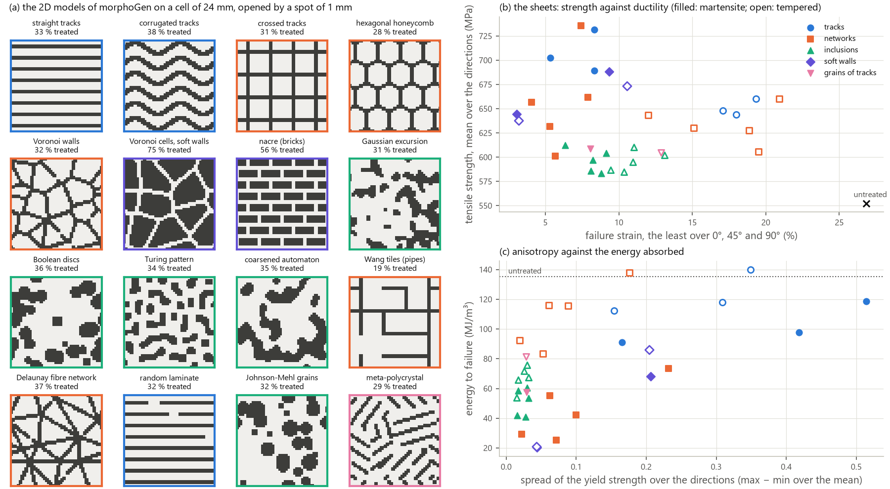
Four rules come out of the table, independent of the model that draws the design:
Strength needs a hard phase connected along the load. Isolated hard islands (Boolean discs, the Gaussian excursion, the Turing pattern, the automaton, Johnson–Mehl grains), a third of the sheet, raise the yield strength by 7 to 14 % only: the soft matrix percolates and yields first, at its own stress, the islands adding hardening (
R_m+6 to +11 %). Tracks along the load raise it by 72 % (517 MPa), networks by 3 to 37 % depending on the direction (the honeycombs and the Voronoi walls by 10 to 18 % in every direction).A connected hard phase must be tough. With the as-quenched martensite, the networks break at 4 to 8 % in their weakest direction (Voronoi walls 5.3 %, Delaunay fibres 4.1 %) and the tracks along the load at 8.3 %, the strain of §5; the same networks of a tempered martensite reach 12 to 21 % in their weakest direction, the honeycomb and the Wang tiles about 20 % in every direction. The architecture of a steel sheet and the toughness of its hard phase are designed together: as in §5, a treatment that leaves the hard phase tougher (a tempered track, a level of a multi-level treatment) is worth more than a harder one.
Thin soft layers across the load localize. Hard cells in soft walls 1 mm wide fail at 3 to 5 % whatever the toughness of the cells: the strain gathers in the walls (nacre, with more mortar, at 9 to 16 %). A soft phase thinner than a few spots must not cut the load path; in nacre the toughening of a natural composite needs weak interfaces that a laser-treated steel does not have (as in the Mg–Ti composites of Zhang et al. 2022, where brick and mortar is the least tough).
Isotropy costs strength unless the network carries it. The meta-polycrystal is isotropic (yield within 3 %, Lankford’s coefficient within 13 to 19 %) but no stronger than the islands (its tracks are cut at the grain boundaries, and the matrix percolates between them); the hexagonal honeycomb and the Wang tiles are isotropic within 6 to 10 % and, tempered, absorb 116 MJ/m³ at
R_m= 606 to 628 MPa. Along the tracks, straight tracks of tempered martensite make the strongest and most ductile of the tempered sheets (444 MPa, 19 to 29 %, 140 MJ/m³, more than the untreated sheet with its law of exponent 0.24), with the anisotropy of §10.
14.3 Steering a ductile crack. The crack of a compact tension specimen (W = 30 mm,
examples/laser_crack_paths.py) grows by the breaking of the elements (the matrix at an
averaged plastic strain of 0.5, §10), with a design of 1 mm over its ligament
(figure). In a hard sheet (contrast_phases(c), graded) a soft corridor 2 mm wide from
the tip, at an angle to the crack, takes it from c = 3 on: the crack runs in the
corridor (72 to 94 % of its broken elements) and turns with it up to 60° (the direction
of the crack and its share in the corridor, corridors 2 mm wide, elements of 0.5 mm):
corridor |
|
|
|
|---|---|---|---|
15° |
10.6° (82 %) |
11.5° (94 %) |
13.4° (93 %) |
30° |
18.7° (71 %) |
24.0° (83 %) |
19.8° (82 %) |
45° |
3.1° (24 %) |
38.8° (82 %) |
31.5° (72 %) |
60° |
−2.9° (27 %) |
66.3° (93 %) |
59.3° (83 %) |
work to separation, 60° (J) |
20.6 |
20.2 |
18.0 |
fully treated (J) |
24.0 |
10.8 |
14.6 |
On elements of 0.25 mm the crack follows the corridors of c = 3 and 4 as closely
(21.7°, 34.9° and 60.3° at 30°, 45° and 60° for c = 3; 20.2° and 58.3° at 30° and
60° for c = 4; 69 to 100 % in the corridor), but no longer those of c = 2 (3.6° at
30°, 40 % in the corridor): the drift of the coarse mesh at c = 2 is an artefact of
the erosion, and the threshold of steering lies between c = 2 and 3. The strength
mismatch decides, as in welds, where a ductile crack drifts towards the softer material
(Minami et al. 1995; Nègre, Steglich & Brocks 2005): a corridor of the matrix in a sheet
three times as strong leads the crack up to 60° from the path of mode I. Corridors 1 mm wide steer as well (62.7° and 64.4° at 60°,
c = 3 and 4), corridors 3 mm wide less at large angles (not at 60° for c = 3). The
cost depends on the angle: a corridor near the path of mode I lets the
crack through for less work than the hard sheet (6.5 against 10.8 J at 15°, c = 3),
a steep one makes it run in mixed mode, longer, for more (20.2 J at 60°, +87 %): a
corridor can lead a crack where it does least harm, or make it spend more. Turning a
crack further takes a gentle curve: an arc of 8 mm radius turning by 90° held it over
its first part only (63 to 66 % of the crack in the arc at c = 3 and 4) before the
crack left it along the path of mode I, and a corridor that ends after 6 mm deflects
the crack, which then crosses the tough hard sheet straight (no arrest). Hard walls along a corridor in the untreated sheet do not steer (the crack
crosses or passes them, 21 to 43 % in the corridor), consistently with §10 (the CT
opening keeps the crack in mode I and the hard walls act as bridges); staggered hard
bricks halve the work (0.53 of the untreated sheet): the crack runs in the mortar. The
rules of thumb of §10 extend to growth: a soft path in a tough hard sheet guides the
crack; hard features in a soft sheet bridge or blunt it; thin soft layers attract it.
Kolednik’s soft interlayers across the path (Sistaninia & Kolednik 2014, 2017) are the
complementary design: a soft band crossed by the crack shields it once crossed.
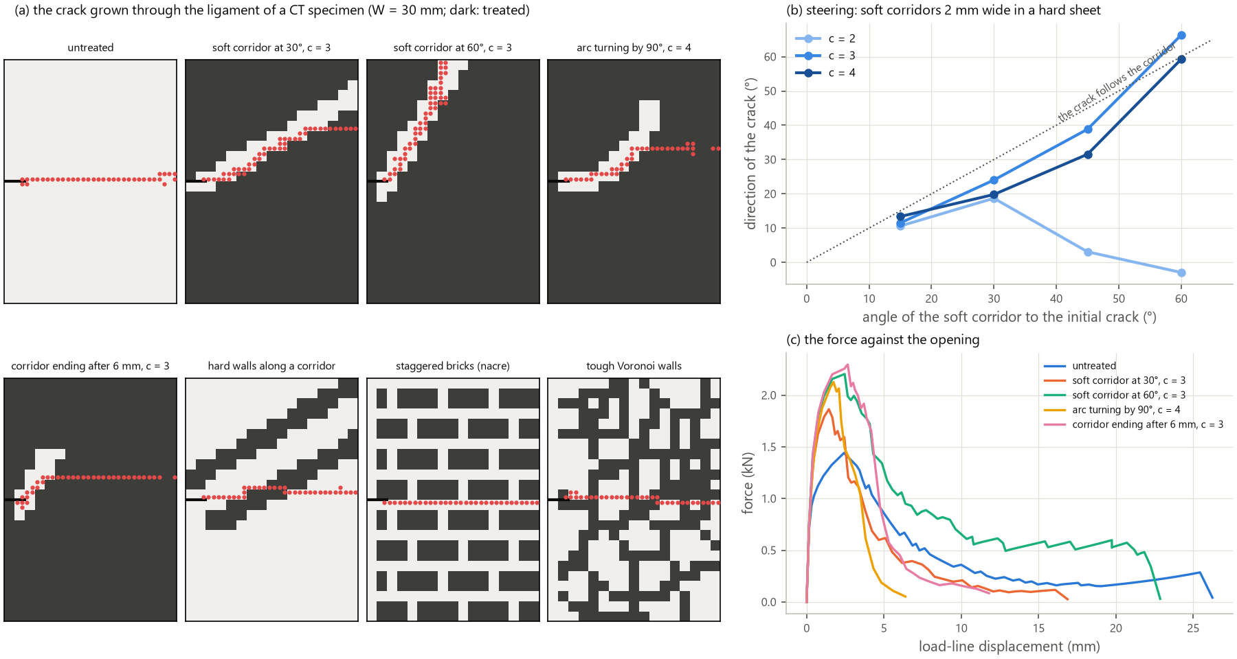
14.4 Stiffness. The phases of a laser-treated steel share Young’s modulus: the
martensite is about 3 % below the ferrite–pearlite (Kim & Johnson 2007), the nitrides
and carbides of carburized or nitrided layers no stiffer than ferrite (γ′-Fe4N about
160 GPa), the austenite within a few per cent. morphoGen’s FFT homogenization of the
designs (examples/laser_stiffness.py, a plane-stress stiffness condensed from the
periodic cell) puts every steel sheet between 205.5 and 208.8 GPa, isotropic: a
stiffness architecture in steel can only come from the geometry of the sheet or from the
residual strains of the tracks (the eigenstrains that program buckled shapes in
metallic glass ribbons, Li et al. 2022). Two systems have a laser-switchable modulus
through the thickness of a sheet: a metastable beta titanium aged then solution-treated
by the laser (Ti-15V-3Cr-3Sn-3Al: 107 to 111 GPa aged, 82 GPa solution-treated; laser
stiffness gradients in aged beta alloys: da Costa et al. 2020), and NiTi, superelastic
austenite at about 68 GPa against martensite at 25 to 40 GPa in tension, made
martensitic at room temperature by laser pulses that evaporate nickel (Khan, Pequegnat &
Zhou 2013; Šittner et al. 2014). With the designs of §14.1: beta titanium sheets of 88
to 103 GPa (spread over the directions 2 % at most), NiTi sheets of 37 to 57 GPa, the
straight tracks anisotropic by 13 % with Poisson’s ratio from 0.30 to 0.36. Elastic
architectures are realistic in NiTi (nonlinear and temperature dependent), structural
but weak in beta titanium; the treated fraction, a gradient over the sheet, is their
main lever.
14.5 Materials to test. The largest property contrasts through the thickness of a sheet come from transformations that complete within the dwell of a laser (a survey of 88 references):
material and treatment |
contrast |
why |
|---|---|---|
annealed C–Mn–B steel (MS1500, 22MnB5): martensite and tempered martensite |
|
three levels in one sheet, the toughness that rules 2 and §14.3 ask for; process mastered at PIMM |
cold-rolled metastable austenitic steel (301, 301LN) with laser reversion |
yield ≥ 965 MPa and 9 % (full hard) against 300 to 1000 MPa and up to 43 % (reverted at 700 to 1000 °C for 1 to 100 s: Somani et al. 2009; Järvenpää et al. 2020) |
no quench, no hardenability limit; reverted austenite paramagnetic in a ferromagnetic matrix: the architecture read by magnetic imaging (Leskovšek et al. 2016) |
aged metastable beta titanium (Ti-15-3) with laser solution treatment |
yield 965–1172 → 770 MPa, 5–7 → 22 %, E 107–111 → 82 GPa |
the only structural alloy with a modulus contrast through the thickness |
NiTi strip, laser nickel depletion or local annealing |
E about 68 against 25–40 GPa; superelastic, shape memory and elastic domains in one strip (Meng et al. 2012) |
an elastic and functional demonstrator |
The aluminium alloys are poor candidates: the laser only dissolves or overages their precipitates, by 30 to 35 % at most, the dissolved state re-ageing at room temperature; AA2024-T3 loses at most 20 % of its hardness and 3 % of its strength, and cracks when it melts (Kashaev et al. 2021), which accounts for the unsuccessful trials at PIMM. Its documented use is the residual stress of laser heating lines (+285 % of fatigue crack growth life). For a feature of 1 mm, the time of diffusion across half a millimetre is about 0.04 s in steel and 0.004 s in aluminium: an aluminium sheet spreads the heat sideways as fast as through its thickness (softened zones of about 5 mm).
14.6 A demonstrator. The results above make a programme of three sheets. (1) An
annealed MS1500 sheet of 300 × 300 × 1 mm with three levels (untreated, tempered and
as-quenched martensite), treated with zones of straight and corrugated tracks
(directional strength and ductility), of a honeycomb or Wang tiles of tempered tracks
(isotropic strengthening at about 20 % of failure strain) and of soft corridors in a
tempered field ahead of notches (CT or SENT specimens cut from the sheet, a crack led
at 30° to 60°), tested with DIC in the directions of §10 and on crack paths
(examples/laser_demonstrator.py, figure: 40 % of the sheet treated, about 1 h of beam
time at 10 mm/s with a spot of 1 mm, the pauses between neighbouring tracks aside). (2) A
cold-rolled 301LN sheet with reverted tracks, the same designs read magnetically
during loading. (3) A NiTi strip with an elastic gradient. Steps of the model: the
toughness of the tempered states (the graded rule of §5 to be measured), the
heat-affected zone of the process model on the designs (the soft walls of rule 3), a
ductile damage law with the triaxiality (Rice–Tracey, GTN) in place of the critical
strain for the crack paths (element erosion biases them towards the mesh: Pandolfi,
Weinberg & Ortiz 2021), and the residual stresses of the tracks.
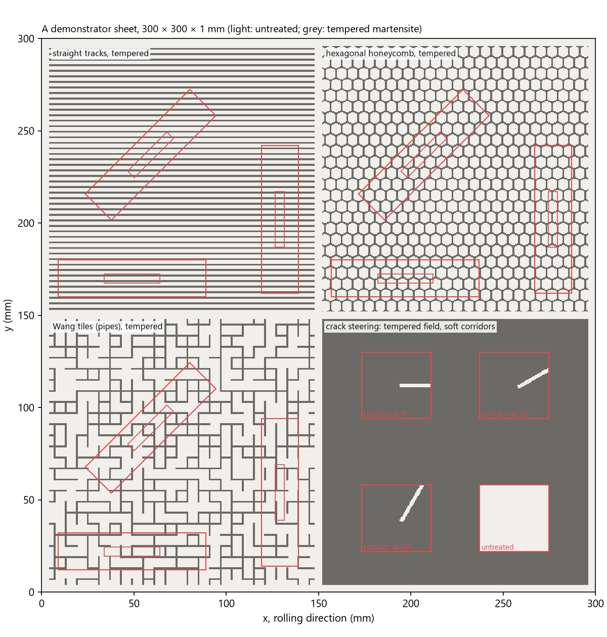
15. Geometric work hardening in one laser-treated steel¶
The idea. A corrugated reinforcement in a matrix that flows first bends at its
crests, then straightens towards the load: it turns from an ineffective orientation to
an effective one, and the composite hardens by its changing geometry when its
materials alone no longer would (geometrically induced work hardening; Bouaziz 2013).
Fraser et al. (2014, 2018a, 2018b, 2020) built it with two metals, a copper matrix
(E 115 GPa, yield stress 25 MPa, K 540 MPa, n 0.53) and a 4130 steel reinforcement
(207 GPa, 350 MPa, 1200 MPa, 0.12), and charted when it pays (in sections of a laminate,
plane strain): the reinforcement must stay
nearly elastic while its crests bend (a yield stress above a threshold), and the matrix
must neither neck before the corrugation has straightened nor harden so much that the
boost comes too late (a window of its yield stress over its hardening). Wang et al.
(2023) obtained it in one steel, laser martensite in annealed MS1500, with one track in
the 5 mm gauge of a dog-bone (§4, §5), where the height over the period stays below
0.15, short of the threshold of Fraser et al. (a height peak to trough of 0.35 period,
H/P = 0.175 here). Two questions: which contrast between the phases unbends the
corrugation, their stiffness or their strength; and what a sheet of tens of
centimetres, free of the gauge, allows (examples/laser_geometric_hardening.py,
morphogen.laser.architectures.track_membrane: smooth tracks over a periodic cell,
phases of different moduli, a treatment that changes along a track).
15.1 Which contrast unbends the tracks. A contrast of Young’s moduli makes the
stresses heterogeneous at a given strain, and the strains at a given stress, but only
while the phases are elastic: once a phase yields, its stress follows its flow law,
whatever its modulus. The matrix of the steel yields at a strain of 0.13 % (280 MPa over
210 GPa), the martensite at 0.6 %, and the geometric hardening plays out between 5 and
40 %. Over that range the contrast of current stiffness is that of a track still elastic,
its Young’s modulus, against a matrix that flows, its hardening (2140, 1310 and 790 MPa
at 5, 10 and 20 % in the annealed MS1500): a ratio of about 100, 160 and 270, and 180,
250 and 340 for the copper and steel of Fraser et al. The plasticity of the matrix makes
this contrast, and the strength contrast keeps the tracks elastic while it lasts. The
study stiffness tests it at 24 % of martensite, P = 20 mm and the ductile rule (the
necking isolated): the modulus of the tracks from 70 to 630 GPa at fixed flow laws, a
matrix of 70 GPa, and moduli in a ratio of 3 with the matrix’s flow law in both phases
(the stiffness contrast alone); the proof stress is read on the initial slope of each
curve (third figure, c):
moduli, matrix and tracks (GPa) |
modulus of the sheet, straight / |
|
uniform elongation, straight / 0.2 / 0.25 (%) |
energy, |
|---|---|---|---|---|
210 and 70 |
175 / 156 |
324 / 312 |
16.9 / 28.8 / 31.0 |
187 |
210 and 117 |
187 / 181 |
369 / 319 |
16.7 / 28.3 / 30.5 |
185 |
210 and 210 (one steel) |
210 / 210 |
464 / 327 |
16.5 / 28.0 / 30.2 |
184 |
210 and 420 |
263 / 246 |
567 / 336 |
16.4 / 27.7 / 30.1 |
184 |
210 and 630 |
315 / 268 |
571 / 340 |
16.4 / 27.7 / 30.1 |
184 |
70 and 210 |
105 / 89 |
567 / 332 |
16.9 / 28.3 / 30.7 |
185 |
210 and 630, one flow law |
315 / 268 |
299 / 301 |
26.8 / 26.8 / 26.8 |
135 |
70 and 210, one flow law |
105 / 89 |
291 / 299 |
27.4 / 27.4 / 27.4 |
137 |
The modulus of the tracks hardly moves the geometric hardening. From 70 to 630 GPa, a factor of 9, the uniform elongation of the corrugated sheet falls by 0.9 point (31.0 to 30.1 % at
H/P= 0.25) and its energy by 2 %, while the corrugation adds about 14 points to the straight tracks at every modulus; the softer tracks gain their larger elastic strain (σ_y/E: 1.9 % at 70 GPa, 0.2 % at 630 GPa). A softer matrix adds its own elastic strain, 0.4 point at 70 GPa (the 117 GPa of Fraser’s copper in the ratio of his steel: 16.7 and 28.1 % atH/P= 0.2; figure, d).The modulus acts at the start of the curve. It sets the modulus of the sheet (the rule of mixtures along straight tracks, less with corrugated tracks, which bend) and the proof stress of straight tracks, from 324 to 571 MPa: a stiffer track takes its share of the load at a smaller strain, a softer one is still elastic at the offset of 0.2 %. Corrugated tracks carry little at that stage, and their proof stress moves less (312 to 340 MPa).
Without a strength contrast, nothing is left beyond the elastic range. With one flow law, moduli in a ratio of 3 either way give the untreated sheet’s uniform elongation and energy (26.8 to 27.4 %, 135 to 137 MJ/m³), straight or corrugated; the extra 0.6 point with a matrix of 70 GPa is its elastic strain.
The partition of the stresses and the strains between the phases shows why (third
figure, a and b: the mean axial stress of the treated material over that of the
untreated, and the mean equivalent strain of the untreated over that of the treated,
against the strain of the sheet). With one flow law and moduli in a ratio of 3, straight
tracks carry 2.7 times the stress of the matrix (the ratio of 3 diluted by the mixed
points at their edges), and around corrugated tracks the matrix strains twice as much as
they do: the heterogeneity of the elastic range. It vanishes as the phases yield: beyond
1 % of strain both ratios stay between 1.0 and 1.15, the flow stress, the same in both,
capping the stresses. With a strength contrast and one modulus, the ratios stay at 1 in
the elastic range and grow once the matrix yields: corrugated tracks carry about twice
the stress of the matrix from 10 % of strain on, while the matrix strains up to nine
times as much as they do (at 5 %): they turn rather than stretch. Stiffer tracks
(630 GPa) strain less still, twelve times less than the matrix at 5 %, but carry the same
stress (a ratio of 2.0). The modulus of a track sets how much it stretches, its strength
how much it carries, and the hardening of the sheet lies in what the tracks carry: while
a corrugated track unbends, the force it transmits along the load is bounded by the
plastic moment of its crests over its current height, σ_y t²/(4H) per unit thickness,
which holds no modulus. A stiffness contrast would count where the reinforcement stays
elastic over strains of the order of the slack (fibres in an elastomer, the crimped
fibres of a tendon), not between metals, whose elastic strains stay near 1 %; the laser
states of one steel differ in modulus by a few per cent, 10 % at most (the survey of
§14, Table 2). The strength contrast does it all, and the laser provides it. In the charts of Fraser et al. (2020: linear
hardening, a matrix yield stress of 300 MPa), the annealed MS1500 (Considère’s strain
0.235, a linear hardening of about 390 MPa at that yield stress) lies in the window
where corrugation pays for a reinforcement above about 600 MPa: the laser martensite
(1300 MPa) and its tempered states of a contrast above about 2.
15.2 What the sheet changes. A corrugation y = H sin(2π x/P) made by a track
t = 1 mm wide has a slack, the strain that straightens it free, L/P − 1 (L its
length over a period): 9 % at H/P = 0.1, 32 % at 0.2, 46 % at 0.25, 62 % at 0.3; its
flanks start at atan(2π H/P) from the load (32°, 51°, 57°, 62°); its crests have a
radius P/(4π² H/P), at least 1.5 mm to be treated (§5): H/P up to 0.17 at P =
10 mm, 0.34 at 20 mm, 0.51 at 30 mm. In a sheet the gauge no longer bounds the height,
and the longer periods reach the whole range of Fraser’s charts. Straightened
completely, a crest would bend its track by t/(2R): 10 % at H/P = 0.1 and 20 % at
0.2 for P = 20 mm, more than the as-quenched martensite takes (7.2 %).
15.3 The sheet of corrugated tracks. The periodic cell holds one period and one
track, the tracks in phase, their spacing setting the treated fraction; cells of 2 × 2
to 4 × 4 periods with an imperfection of 0.5 % in one period give the same uniform
elongation within 0.2 point (the failure strain of the most corrugated martensite 2
points lower), elements of 0.25 mm within 2.1 points (the strengths within 15 MPa).
24 % of martensite, R_m (MPa) / failure strain (%) / energy up to it (MJ/m³), under
the two rules of §5 (ductile: the necking alone, the bound of the geometric
hardening; graded: the as-quenched martensite breaks at 0.072, the fit to the tests of
Wang et al.; figure, a to c):
design |
ductile |
graded |
|---|---|---|
untreated sheet |
552 / 26.8 / 135 |
552 / 26.8 / 135 |
straight tracks |
783 / 16.5 / 121 |
764 / 8.3 / 57 |
|
760 / 19.6 / 137 |
722 / 7.9 / 50 |
|
703 / 28.0 / 179 |
652 / 10.4 / 57 |
|
665 / 30.2 / 184 |
639 / 14.2 / 79 |
|
632 / 27.5 / 160 |
627 / 19.5 / 109 |
|
665 / 32.1 / 196 |
627 / 11.8 / 64 |
The geometric hardening of one steel matches that of two metals. Ductile, the corrugation turns the early necking of the straight tracks (16.5 %) into a uniform elongation above the matrix’s from
H/P= 0.2 on, with a tensile strength 20 to 27 % above it: the sheet is both stronger and more ductile than when untreated, the hole in property space of Fraser et al. (2018a). At 36 % (P= 30 mm,H/P= 0.25): 716 MPa, 39.4 % and 266 MJ/m³, twice the energy of the untreated sheet. The yield strength falls back near the matrix’s (459 MPa straight, 321 to 351 MPa corrugated): the corrugation trades yield strength for hardening, as Wang et al. measured.An optimum height, set by the slack. The uniform elongation peaks at
H/P= 0.25 (a slack of 46 %) and falls at 0.3, where the boost comes after the matrix has necked (the bound foreseen by Fraser et al. 2018b). At a givenH/Pthe period matters little (2 points at most up to 0.2). There is no threshold against the straight tracks, whose martensite necks early (unlike Fraser’s steel in copper); the corrugation passes the matrix’s uniform elongation atH/P≈ 0.2.The strength contrast sets the size of the boost. Ductile, the best feasible design at 36 % absorbs 266, 180 and 151 MJ/m³ for contrasts of 4.64, 4 and 3 (straight tracks: 114, 126 and 135): the threshold of the reinforcement’s yield stress of Fraser et al. (2020) appears as a continuous trend.
The as-quenched martensite breaks at the crests. Graded, the first fracture lies at a crest, where the track bends (a plastic strain of 0.09 to 0.17 there), while the flanks stay elastic: the tracks unbend rather than stretch, as the mechanism requires, but their hinges crack. The failure strain rises with the height (8.3 % straight, 19.5 % at
P= 20 mm andH/P= 0.3), short of the matrix’s, and so does the energy (109 MJ/m³ against 135). A tempered reinforcement of contrast 3 (its critical strain 0.24 under the graded rule) does not break before the necking: 633 MPa, 25.6 % and 148 MJ/m³ at 24 % (P= 30 mm,H/P= 0.2), 676 MPa, 24.3 % and 151 MJ/m³ at 36 %, the energy 10 % above the untreated sheet at a strength 15 to 22 % higher. As in §5, the toughness of the treated states decides, and is to be measured.
15.4 A track treated differently along its path. Only the laser can soften a
reinforcement where it bends: the crests treated at a lower energy (tempered, contrasts
of 2 and 3) or left untreated, the flanks as-quenched (track_membrane with two treated
phases). At 24 % and P = 20 mm (second figure, b), tempering the crests over a quarter
of the period about each rescues the martensite: at H/P = 0.25 the failure strain
rises from 14.2 to 26.4 %, at 628 MPa and 152 MJ/m³ (14 % stronger than the untreated
sheet, 13 % more energy, nearly its failure strain), slightly beyond a track tempered
all along (25.3 %, 618 MPa, 143 MJ/m³); at the other heights the uniform temper does as
well or better. Over an eighth of the period, the softer hinge concentrates the bending
and breaks itself at the crest (14.2 % at H/P = 0.2, 18.6 % at 0.25). Untreated crests
leave pieces of oblique martensite (15 to 21 % of the sheet treated) and reach 21 to
23 %. The gain over the as-quenched track is large; the gain over a uniform temper is
small, and rests like it on the toughness assumed for the tempered state.
15.5 Recruitment does not pay. Tracks of two to four heights in one cell straighten one after another, as the crimped fibres of a tendon, and spread the boost over a wider range of strain. Ductile, they reach 22.3 to 26.4 % at 24 %, below the best single height (30.2 %); graded they do worse (6.6 to 9.8 %), the least corrugated tracks straightening first and breaking. The boost pays when it is concentrated and timed to the necking of the matrix.
15.6 A check against Fraser et al. Their copper with 20 % of steel in the periodic
sheet (second figure, a) (P = 8 mm, one reinforcement every 5 mm, its width keeping the fraction):
necking strains of 40.5 % straight and 55.2 % at a height of 4 mm peak to trough,
against their 40 % and about 55 % (Fraser et al. 2018b, Fig. 3a), and hardly any gain
below a height of 2 mm (their threshold, h/P = 0.35). Their plane-strain sections and
this plane-stress sheet agree on the necking strains; the stresses differ by the factor
of plane strain.
15.7 Specimens. A dog-bone cut from the sheet holds tracks up to its edges, where the
soft channels between them reach the free edge: the necking starts there (maps of the
plastic strain). Ductile, at 24 % and P = 20 mm (second figure, c): 18.0 % at H/P =
0.2 with four tracks across the gauge (22 mm), 23.0 % with eight (44 mm), 28.0 % for the
sheet; 21.4, 24.3 and 27.5 % at 0.3; the straight tracks match the sheet (16.7 and
16.4 % against 16.5 %). Graded, eight tracks give 8.2 and 14.8 % against the sheet’s
10.4 and 19.5 %. A border of tempered martensite 2 mm wide along each edge does worse
(20.9 and 16.9 %): a straight hard band necks first. A test of the sheet needs specimens
of eight tracks or more, read by DIC away from the edges, and the cut edges of a part
are its weak points.
15.8 What to treat. A zone of the demonstrator of §14.6: corrugated tracks at P =
20 mm and H/P = 0.25 and 0.3 (crest radii of 2.0 and 1.7 mm), 24 and 36 %,
as-quenched, tempered, and as-quenched with tempered crests (the power lowered over a quarter of the period about each crest); dog-bones of eight tracks or more (about 50 mm wide
and 90 mm long) with DIC on the hinges, and the straight tracks and the untreated sheet
for reference. The fracture of the hinges under bending, and of the tempered states, is
the decisive unknown: the graded rule is an assumption.
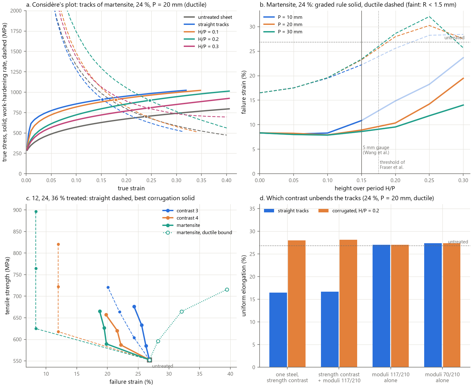
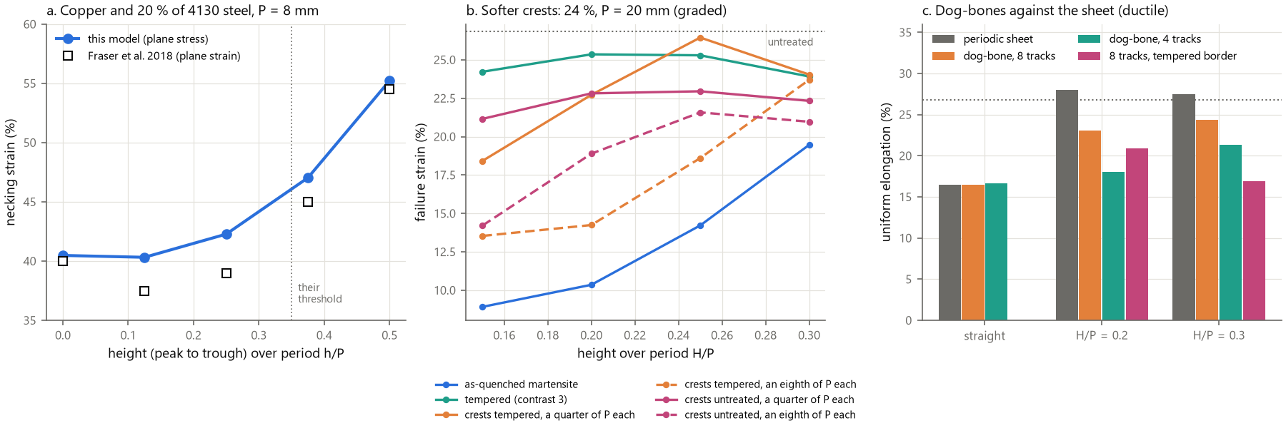
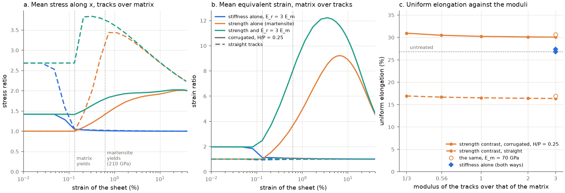
16. Where geometric hardening works: directions, networks, forming¶
The questions. The corrugated tracks of §15 harden the sheet along their axis, in
uniaxial tension. A part is loaded in other directions too, and a sheet is formed along
biaxial paths. Three questions follow: how the corrugated sheet behaves away from its
axis; whether networks of corrugated tracks spread the effect over the plane; what
happens along the paths of forming (examples/laser_networks.py,
examples/laser_networks_figure.py). The designs treat 24 % of the sheet with tracks
1 mm wide, of as-quenched martensite (ductile and graded) or tempered (contrast 3,
breaking at 0.24): one family (P = 20 mm, §15), a square network (two families along x
and y, two tracks of each per period, the second a quarter of a period behind, so that the
families cross instead of running along each other) and a triangular network (three
families at 0, 60 and 120° through the nodes of a triangular lattice, one wave between two
nodes; it is chiral, its directions repeat every 60° without mirroring), their period or
side scaled so that the crossing tracks treat 24 % (23.7 and 20.5 mm at H/P = 0.25).
16.1 Away from the axis. The periodic sheets pulled in the directions of the plane (the angle from the tracks along x): the failure strain (%) with the ductile reinforcement, and the least and the largest energy to fracture (MJ/m³) and tensile strength (MPa) over the directions with the tempered one (the untreated sheet: 26.8 %, 135 MJ/m³ and 552 MPa in every direction; figure, a and b):
design, 24 % |
0° |
15° |
30° |
45° |
60° |
75° |
90° |
energy, tempered |
|
|---|---|---|---|---|---|---|---|---|---|
straight tracks |
16.5 |
17.6 |
22.2 |
35.3 |
23.3 |
16.4 |
18.2 |
97 to 157 |
576 to 664 |
corrugated tracks, |
30.3 |
14.6 |
11.8 |
16.1 |
16.6 |
19.3 |
18.2 |
93 to 143 |
606 to 625 |
square network, straight |
17.7 |
17.1 |
22.2 |
26.7 |
22.2 |
17.1 |
17.7 |
122 to 152 |
620 to 643 |
square network, |
18.4 |
11.0 |
11.8 |
16.1 |
13.9 |
18.4 |
22.2 |
98 to 122 |
612 to 622 |
triangular network, straight |
23.3 |
18.3 |
10.7 |
19.1 |
23.3 |
18.3 |
10.7 |
115 to 131 |
612 to 638 |
triangular network, |
17.1 |
19.5 |
14.7 |
16.1 |
17.1 |
19.5 |
14.7 |
109 to 121 |
614 to 618 |
The corrugation pays along its axis only. 30.3 % at 0°, 14.6 % at 15° already, 12 to 19 % beyond: within 15° of the axis the gain turns into a loss.
Straight tracks oblique to the load harden late. At 45° straight tracks reach 35.3 %, 674 MPa and 215 MJ/m³ (ductile), more than the corrugation along its axis, and the as-quenched martensite does not break there (35.3 % as well, against 8.3 % along the load). The sheet shears (freely, in the periodic cell) and holds its tracks on a line it hardly stretches, by 0.5 % at a strain of 15 % and 2.2 % at 30 %, while they turn by 13° towards the load; the straight tracks of §14.2 at 45° (30.3 %) showed the same effect. At 30° the tracks stretch from the start (6.3 % at 15 %), at 60° they are still unstretched at 30 %: 22.2 and 23.3 %.
No network hardens geometrically, in any direction. With the ductile reinforcement the corrugated square network fails between 11 and 22 % depending on the direction and the triangular one between 15 and 20 %, below the untreated sheet; in every direction one family is stretched from the start (the flanks of the family along y lie at 33° from a load along x; the families at 60 and 120° run at 2.5° from x along part of their length). The triangular network of tempered tracks makes the most isotropic sheet (failure strains of 19 to 22 %, 109 to 121 MJ/m³, in every direction), 11 % stronger than the untreated sheet but not tougher.
16.2 The forming limits. cell_test(ratio=...) follows linear paths of the true
strains, ln(1 + b) = ρ ln(1 + a), from plane strain (ρ = 0) to equibiaxial stretching
(1), the stress along the major strain being the mean nominal stress of the cell
(mean_nominal). The Marciniak–Kuczyński analysis is made in the cell: a groove 1 mm
wide (the thickness of the sheet), normal to the major strain, its flow stress 0.5 %
lower, across a cell of at least two periods and 60 mm. The limit is the strain outside
the band of 1 mm that strains ten times faster than its images in the other periods (the
groove, or a neck elsewhere: a neck breaks the periodicity of the pattern, whereas a band
that strains faster in every period is a partition of the strains), the strain at which
the path can no longer be followed (the rest of the cell unloading elastically as the neck
softens), or the fracture of the reinforcement, whichever comes first. On the untreated
sheet the groove in the cell gives the classical analysis (rigid plastic, von Mises, the
Swift law of the matrix, the same imperfection: 0.190, 0.256, 0.397, 0.535 and 0.647 from
ρ = 0 to 1) within 0.004 from ρ = 0.25 to 1 and 0.006 in plane strain, on cells of 50
to 200 mm (20 mm: up to 0.024 above; --study mk). The major true strain at the limit,
ductile reinforcement (figure, c):
design, 24 % |
|
0.25 |
0.5 |
0.75 |
1 |
|---|---|---|---|---|---|
untreated sheet |
0.195 |
0.256 |
0.397 |
0.537 |
0.650 |
straight tracks, major strain along them |
0.128 |
0.145 |
0.176 |
0.198 |
0.211 |
straight tracks, across |
0.118 |
0.138 |
0.183 |
0.241 |
0.294 |
corrugated tracks |
0.120 |
0.155 |
0.223 |
0.295 |
0.358 |
corrugated tracks, across |
0.074 |
0.089 |
0.112 |
0.135 |
0.159 |
square network |
0.065 |
0.077 |
0.102 |
0.122 |
0.142 |
triangular network |
0.077 |
0.087 |
0.110 |
0.214 |
0.234 |
triangular network, along y |
0.074 |
0.081 |
0.123 |
0.198 |
0.252 |
Every architecture lowers the forming limit on the stretching side: 0.07 to 0.13 in plane strain against 0.195, 0.14 to 0.36 in equibiaxial stretching against 0.65. The tempered reinforcement does little better (0.10 to 0.17 in plane strain, 0.15 to 0.28 in equibiaxial stretching; straight tracks along the major strain break at about 0.20 from
ρ= 0.25 on). The necks form in the matrix along the hard tracks, along the flanks of a corrugation in plane strain.The corrugation does not unbend before it stretches. Along its axis it raises the limit over straight tracks on the biaxial side (0.358 against 0.211 at
ρ= 1), where straight martensite stretches with the sheet and necks with its own low hardening, but not in plane strain (0.120 against 0.128); across its axis it is the least formable family (0.074 in plane strain).The networks are the least formable (0.065 to 0.077 in plane strain): the matrix enclosed in their cells is held in every direction.
16.3 The rule: lines that the deformation shortens. Under the homogeneous true strains
ε1 and ρ ε1, a material line at an angle φ from the major strain stretches by
(e^(2ε1) cos²φ + e^(2ρε1) sin²φ)^½ (figure, d). For ρ < 0 the lines beyond φ0 = atan (−1/ρ)^½ are first shortened, then turned towards the major strain, and stretched:
54.7° in uniaxial tension (ρ = −½, plastic incompressibility), 45° in a section in plane
strain (ρ = −1, the sections of Fraser et al.); these are the directions of zero
extension along which Hill (1952) placed the localized neck of a sheet. For ρ ≥ 0 no
line is shortened: every line stretches from the start (by 16.2 % at a major strain of
0.15 in equibiaxial stretching, whatever its angle). A track along a shortened line
carries little until it has turned, then takes the load: the boost of geometric
hardening, late by the strain it takes to turn. The flanks of a corrugation lie at
atan(2π H/P) from its axis: 54.7° at H/P = 0.225, 45° at 0.159. The rule accounts for
the results of §15 and of this chapter:
at
H/P= 0.25 (57.5°) the flanks are shortened up to a strain of 14.8 % in uniaxial tension, at 0.3 (62°) up to 45 %: the boost of the first comes before the matrix necks (26.8 %), that of the second after it, which makes the optimum and the decline of §15.3; below 0.225 the flanks stretch from the start, and a corrugated track reinforces like a weaker straight one;the threshold of Fraser et al. (a height of 0.35 period peak to trough,
H/P= 0.175, flanks at 47.7°) lies just beyond the 45° of their plane-strain sections, and their corrugations of 2 mm (flanks at 38°) hardly paid in §15.6;off its axis, one flank of a corrugation is stretched from the start, whereas straight tracks oblique to the load lie on a line that the shearing sheet keeps unstretched (16.1);
whatever the direction of a uniaxial load, a network holds one family on stretched lines: the cone of shortened lines turns with the load, so that geometric hardening cannot be isotropic in tension;
the stretching side of forming (
ρ ≥ 0) has no shortened line: no corrugation unbends before it stretches, and the tracks hold the matrix that necks along them.
16.4 Oblique tracks in a specimen. The periodic sheet shears freely; a dog-bone does
not, and its edges cut the tracks (examples/laser_networks_specimen.py: gauges 44 mm
wide and 90 or 180 mm long, straight tracks treating 24 %). Along the load the dog-bones
match the sheet (16.2 and 17.4 % against 16.5 %, ductile; the as-quenched martensite
breaks at 6.2 and 6.3 %). At 45° they reach 25.2 and 26.6 % (ductile), short of the
sheet’s 35.3 %: each track ends at the free edges, where it can carry nothing along its
length, and the longer gauge does not recover it. The as-quenched martensite at 45° still
holds to 23.5 and 24.5 %, against 6.2 % along the load, at 650 MPa and 137 to
143 MJ/m³: 18 % stronger than the untreated sheet for the same energy (135 MJ/m³), with
the hardest state of the laser and no temper. A part whose oblique tracks run on beyond
the loaded zone comes closer to the periodic sheet than a narrow specimen, whose edges
weigh as much as its tracks.
16.5 What it means. The corrugation of a laser track is a directional reinforcement:
for a part loaded in uniaxial tension within a few degrees of the axis of its tracks, its
flanks just beyond the line of zero extension (H/P about 0.25), and for the paths with
ρ < 0 (the flange of a deep-drawn cup, near −1, where flanks beyond 45° suffice: a
prediction, the inclined necks of that side not being computed here). Straight tracks
oblique to the load (about 45°) harden late without a corrugation and spare the
as-quenched martensite, which then needs no temper (16.4). On the stretching side of
forming every architecture lowers the limit: a sheet to be stretched is
treated after forming, or not where it is stretched. Isotropic strengthening comes from
networks of tempered tracks (the triangular one: 11 % of strength, 19 to 22 % of failure
strain in every direction), at a cost in energy, not from geometric hardening. The
networks of wavy struts that give elastomers a J-shaped curve in every direction (Jang et
al. 2015; Ma et al. 2016) rely on struts that bend elastically over strains of the order
of their slack; in a metal sheet the matrix flows, and the kinematics of its flow decide
which tracks carry.
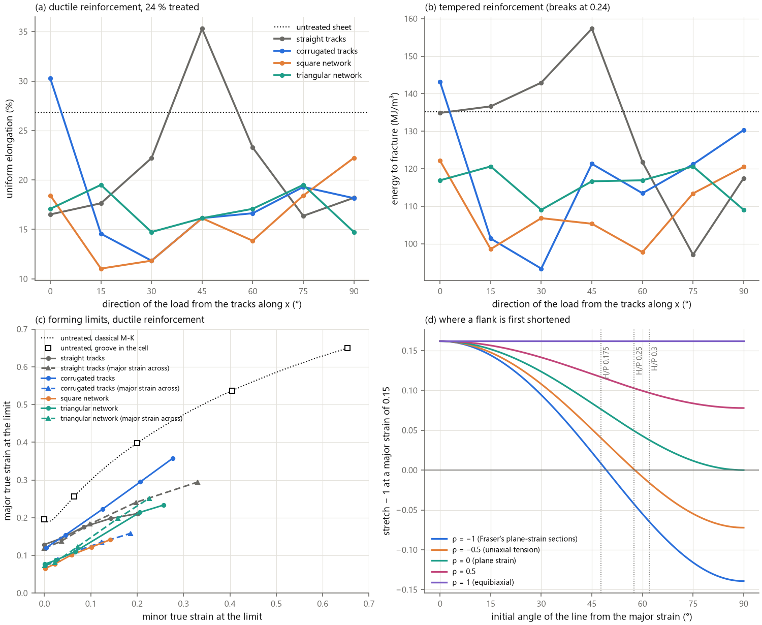
17. The drawing side, and crossed families that lock¶
The questions. On the stretching side of forming every architecture lowers
the forming limit (§16.2), and the rule of §16.3 says why: no line of the sheet is
shortened there. On the drawing side (ρ < 0) the lines beyond φ0 are first
shortened, and the rule predicts that tracks laid there harden the sheet late; but
the necks of that side are inclined (Hill 1952), and the limit is the least over the
angle of the groove (Hutchinson & Neale 1978). Three questions: which designs raise the
limit of the drawing side; whether an architecture can be drawn from the rule itself
rather than from the corrugation; whether it survives the free edges of a specimen
(examples/laser_drawing.py, examples/laser_crossed_specimen.py,
examples/laser_crossed_mechanism.py, examples/laser_drawing_figure.py).
17.1 Inclined grooves in the cell. The groove runs along a vector g of the lattice
of the pattern: any direction for straight tracks, which are invariant along themselves;
for corrugated tracks and crossed families the vectors of their lattice, the shortest
within 2° of the angle asked (from 15° for corrugations: nearer to the normal of their
axis the vectors grow beyond 76 mm). The cell is the parallelogram that g spans with a
vector of the lattice nearly normal to it, 60 mm across, meshed in rows along g
(PeriodicCell.build(shape=...)); the groove is two rows, about 1 mm wide, 0.5 %
weaker. The path of the strains is prescribed in full, the principal axes of the mean
stretch held (cell_test(free_shear=False)), as by the tools of a press and in the
classical analysis; the limit is the major strain outside the band of two rows that
thins ten times faster than its images in the other periods (and than a tenth of the mean
thinning of the cell: the images of a band inside a shortened hard track thicken), as in
§16.2 but on the thickness strain, which an inclined neck concentrates whatever its
shear. On the untreated sheet the cell follows the classical analysis of inclined grooves
(rigid plastic, von Mises, the Swift law of the matrix, the same imperfection;
mk_limit) within 0.007 at every angle and path, and its critical angle: the least
classical limits are 0.358 at 21° in uniaxial tension, 0.294 at 21° at ρ = −⅜, 0.248
at 18° at −¼ and 0.214 at 13° at −⅛, the cell’s 0.362, 0.298, 0.253 and 0.219 on grooves
by the degree; a cell twice as long (0.367 at 20°) or free to shear (0.367) changes
nothing. A groove much beyond the critical angle does not localize: its normal turns with
the sheet, tan ψ = e^((1 − ρ) ε1) tan ψ0, and it passes the line of zero extension
before it necks.
17.2 Single families on the drawing side. The least limit over the grooves (24 %, ductile; untreated 0.362 and 0.253):
design, 24 % |
|
−¼ |
|---|---|---|
straight tracks at 0° from the major strain |
0.214 |
0.162 |
at 30° |
0.243 |
0.180 |
at 45° |
0.288 |
0.201 |
at 60° |
0.291 |
0.195 |
at 75° |
0.225 |
0.173 |
at 90° |
0.250 |
0.178 |
corrugated along the major strain, |
0.360 |
0.210 |
|
0.353 |
0.211 |
|
0.350 |
0.206 |
|
0.328 |
0.183 |
Straight tracks lose at every angle. Of the two critical necks, symmetric about the major strain, one runs within about 10° of a family oblique to the load and follows its matrix: tracks at 60° stop the necks that cross them (no localization for grooves at +10 to +40°) but not the groove at −25° (0.291).
The corrugation keeps the limit of the untreated sheet in uniaxial tension at best (0.35 to 0.36), and loses it towards plane strain, where its flanks lie within the cone of stretched lines (
φ0= 63.4° atρ= −¼).
17.3 Crossed families: a scissor network. The rule asks for tracks along lines that
the deformation first shortens, turning past the line of zero extension when the matrix
would neck. Two families of straight tracks crossed at ±θ about the load lie both in
the cone of shortened lines for θ > φ0, and the network is symmetric about the load, so
that the sheet does not shear. Inextensible tracks would leave the sheet a mechanism: a
mean stretch diag(λ1, λ2) keeps both families at their length when λ1² cos²θ + λ2² sin²θ = 1, the rhombic cells lengthening along the load as their sides turn (lazy
tongs). The matrix contracts as λ2 = λ1^(−½) in uniaxial tension; for θ > φ0 the
mechanism contracts less, the tracks hold the width of the sheet in mild compression
while they turn, until both coincide at cos²θ = 1/(1 + λ + λ²), when the tracks reach
the line of zero extension (the strain at which a line at θ recovers its length,
§16.3): beyond, the network locks and its tracks take the load. Placing the locking at
the necking of the matrix, λ = e^n, gives cos²θ* = 1/(1 + e^n + e^(2n)): 59.5° for
n = 0.24. The periodic sheet pulled along the bisector (--study tension, each family
at the spacing that treats 24 % together, 2t/s − t²/s² = f), R_m (MPa) / uniform
elongation (%) / energy (MJ/m³):
|
ductile |
as-quenched (failure) |
tempered ( |
|---|---|---|---|
untreated sheet |
552 / 26.8 / 135 |
||
45° |
700 / 28.1 / 177 |
693 / 23.6 (20.5) / 125 |
629 / 26.9 / 154 |
55° |
654 / 35.6 / 212 |
651 / 33.2 (29.0) / 168 |
608 / 28.5 / 159 |
57° |
634 / 37.1 / 216 |
||
60° |
606 / 42.9 / 245 |
605 / 42.8 (39.2) / 223 |
585 / 26.9 / 145 |
62° |
607 / 23.4 / 131 |
607 / 23.4 / 131 |
|
65° |
602 / 18.2 / 100 |
602 / 18.2 / 100 |
588 / 20.3 / 109 |
70° |
610 / 16.7 / 92 |
610 / 16.7 / 92 |
594 / 18.5 / 100 |
The best geometric work hardening of the periodic sheet, with straight tracks. At 60° the network beats the best corrugation (665 MPa, 30.2 %, 184 MJ/m³) in uniform elongation and energy, and the as-quenched martensite does not break before the sheet necks (8.3 % along the load). Elements of 0.25 mm: 41.7 % (ductile) and 40.4 % (as-quenched).
A drop just beyond the angle of the rule. 39.3 and 42.9 % at 59 and 60°, 23.4 % at 62° and 18 to 20 % beyond (0.25 mm: 40.7, 41.7, 39.6 and 22.4 % at 59, 60, 61 and 62°): within 2.5° of
θ*, which neglects the stiffness of the matrix in the mechanism. Beyond, the network locks after the matrix has necked, its tracks holding the sheet in compression (−605 MPa at 70°); below, it locks early. At 60° the mean stress along the tracks stays between −116 MPa and zero up to about 10 % of strain, then rises to 1118 MPa.The fraction and the contrast. 33.7 % at 60° and 12 %; at 36 % the optimum moves to 55° or below (37.3 %, 710 MPa, 246 MJ/m³), a denser network holding the contraction more. The tempered state gives 26.9 % at 60°: the boost follows the strength contrast, as for corrugations.
17.4 Specimens: the free edges. In a dog-bone 44 mm wide (gauge 90 mm;
examples/laser_crossed_specimen.py), the network at 60° gives 606 MPa but 23.6 % of
uniform elongation (21.7 % on 180 mm, the tempered state 23.1 and 21.7 %): the free edges
cut the rhombic cells into open half-cells, which the tracks do not close, and the matrix
necks there first while the closed cells of the interior remain held (map). A straight
track along each edge makes it worse (17.1 %, ductile; 9.3 % with as-quenched edges, which
break, 16.7 % with tempered ones): a straight hard band along the load necks first, as in
§15.7. Smaller angles keep the gain: 24.7, 31.5 and 33.3 % at 50, 55 and 57° (675, 640
and 631 MPa; 149, 185 and 194 MJ/m³). At 57° the dog-bone is 14 % stronger than the
untreated sheet, with 24 % more uniform elongation and 44 % more energy, against 23.0 %
for the corrugated tracks of §15.7 in the same dog-bone: the edges move the drop to
smaller angles, and an angle a few degrees below θ* keeps a specimen on the safe side.
The gain holds on a gauge of 180 mm (31.4 % at 57°) and at 58° (32.7 %); in a dog-bone
twice as wide (88 mm), where the edges weigh half as much, the drop moves back towards
θ*: 34.6 %, 622 MPa, 200 MJ/m³ at 60°, 35.2 %, 643 MPa, 208 MJ/m³ at 57°. The
as-quenched martensite, which the ductile rule spares, breaks in the dog-bone: 24.4 % at
57° (627 MPa, 138 MJ/m³, the strength at the energy of the untreated sheet; 15.0 % at
55°); tempered (c = 3), 27.3 %, 601 MPa, 151 MJ/m³.
Away from the edges the network resists the localized neck: under uniaxial stress
(--study uniaxial, the groove in the long cell, the shear free) the least limits are
0.514 at ±60° and 0.489 at ±55°, against 0.365 for the untreated sheet, 0.371 for the
corrugation (H/P 0.25) and 0.344 for straight tracks at 45°.
17.5 Crossed families on the drawing side. Under the paths of forming (the principal axes held), the least limits over the grooves:
design, 24 % |
|
−¼ |
|---|---|---|
untreated sheet |
0.362 |
0.253 |
crossed at ±45° |
0.343 |
0.224 |
±55° |
0.420 |
0.233 |
±60° |
0.449 |
0.235 |
±65° |
0.499 |
0.256 |
±70° |
0.357 |
0.209 |
Each inclined neck runs near one family but crosses the other at a large angle, which
stops it: in uniaxial tension the networks beyond φ0 raise the forming limit (by 16, 24
and 38 % at ±55, ±60 and ±65°); at ±70° the families lie near the direction of the
critical neck, which runs along one of them (a groove at 20°: 0.357). At ρ = −¼, whose
φ0 is 63.4°, the networks at most match the untreated sheet (0.256 at ±65°): the gain is
confined to the neighbourhood of uniaxial tension. The whole drawing side (ρ = −⅜, −⅛
and 0 added) locates its end: the gain vanishes near the path whose line of zero extension
reaches the families, ρ = −cot² θ, between −⅜ and −¼ at ±60° (−⅓) and near −¼ at ±65°
(−0.22; +26 % at −⅜, +1 % at −¼, −18 % at −⅛); the network at ±55° keeps +6 % at −⅜,
beyond its bound (−0.49). In plane strain all networks lie below the untreated sheet
(0.147 to 0.151 against 0.195). Freeing the shear does not save single families: straight
tracks reach at most 0.350 (45°) against 0.362.
A check of the rule on corrugations: θ* places the flanks at H/P = 0.270, but the
uniform elongation peaks at 0.25 and declines slowly beyond (30.2, 30.1, 29.7 and 28.8 %
at 0.25, 0.26, 0.27 and 0.28, 27.5 % at 0.3; examples/laser_corrugation_fine.py): the
crests, which must bend before the flanks carry load, favour a slightly earlier locking,
and the rule gives the order of the optimum, not its exact height. The snapshots of the
cell (examples/laser_cell_fields.py) show the two mechanisms: the matrix strains in bands
along the flanks of corrugated tracks, uniformly inside the rhombic cells of the network,
which holds the width of the sheet before it locks (a lateral contraction of 3.8 % at 10 %
of strain against 4.7 % for the matrix alone, 15.3 % at 40 % against 15.5 %).
17.6 What it means. On the drawing side as on the stretching side, single families
of tracks, straight or corrugated, do not raise the forming limit: the inclined necks find
their way along them. The rule selects a better architecture than the corrugation: two
families of straight tracks crossed just beyond the line of zero extension, a scissor
network that locks at an angle given in closed form; it hardens the sheet late in uniaxial
tension without bending its tracks, spares the as-quenched martensite, raises the forming
limit of the drawing side near uniaxial tension, and keeps its gain in a dog-bone at an
angle a few degrees below θ*. The free edges are its weak points, and those of every
architecture: the gains of the sheet belong to closed sections (tubes, where the
network runs as two helices) and to parts wider than their loaded zone.
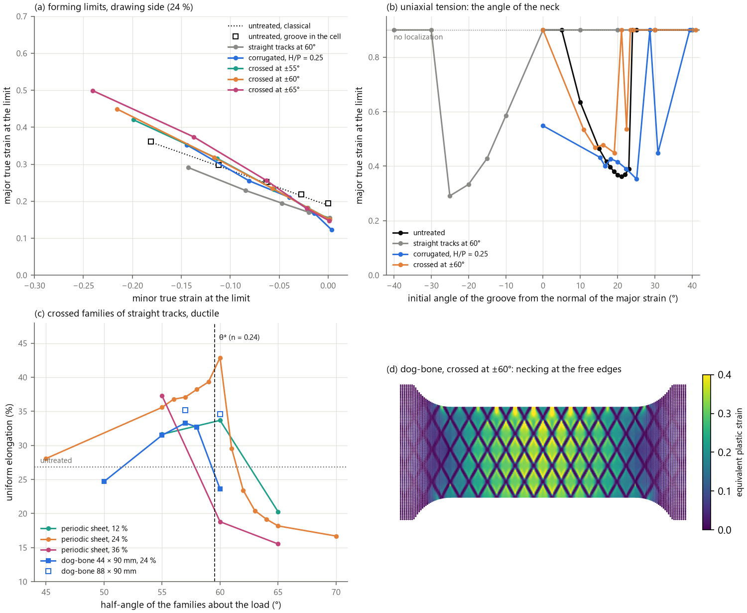
17.7 The treated fraction, full treatment and switched phases
(examples/laser_fraction_inverse.py). Crossed families of 6 to
60 % treated, each over 45 to 65°, periodic sheet, shear free:
treated |
best |
ductile: |
as-quenched: best |
|---|---|---|---|
6 % |
60° |
562 / 31.5 / 164 |
31.5 |
12 % |
60° |
574 / 33.7 / 180 |
33.7 |
18 % |
60° |
588 / 37.2 / 204 |
37.2 |
24 % |
60° |
606 / 42.9 / 245 |
39.2 |
30 % |
60° |
623 / 46.5 / 276 |
36.8 |
36 % |
57.5° |
687 / 37.7 / 245 |
29.9 |
48 % |
55° |
757 / 38.3 / 276 |
26.2 |
60 % |
50° |
931 / 23.9 / 207 |
17.1 |
The optimum lies between 24 and 30 % (30 % ductile, 24 % as-quenched, the martensite of
denser networks breaking first); the best angle stays at 60°, near θ*, up to 30 %, then
falls (a dense network locks later than thin inextensible tracks). Full treatment is not a
solution: the homogeneous sheets, one laser state over the whole sheet, run from 552 MPa
and 26.8 % (untreated) to 1558 MPa and 7.0 % (martensite), their product R_m A_g at most
15.2 GPa % (26.0 for the network at 24 %, 29.0 at 30 %); at equal strength (606 MPa) a
homogeneous sheet reaches 24.9 %, the network 42.9 %. Switching the phases (annealed tracks,
24 %, in a martensite matrix) destroys the effect: straight soft tracks along the load keep
1292 MPa but neck at 8.5 %, crossed soft tracks at ±55 to ±65° neck at 5.0 to 6.4 %
(617 to 636 MPa), the soft network carrying all the strain near the line of zero
extension, at ±45° at 15.5 %. The hard phase must form the mechanism, the soft phase fill
its cells.
References¶
Wang Z. (2022) Architecturation de tôles métalliques par traitement laser localisé. PhD thesis, HESAM Université (ENSAM, PIMM), supervised by J. Dirrenberger. tel-04041478.
Wang Z., Dirrenberger J., Lapouge P., Dubent S. (2022) Laser treatment of 430 ferritic stainless steel for enhanced mechanical properties. Mater. Sci. Eng. A 831, 142205. 10.1016/j.msea.2021.142205
Wang Z., Dirrenberger J., Lapouge P., Dubent S., Jabir H., Michel V. (2022) Microstructure evolution and mechanical properties of AISI 430 ferritic stainless steel strengthened through laser carburization. J. Eng. Mater. Technol. 144, 041005. 10.1115/1.4055025
Wang Z., Bouaziz O., Dirrenberger J., Lapouge P. (2023) Corrugation reinforced architectured materials by direct laser hardening: a study of geometrically induced work hardening in steel. steel res. int. 94, 2200695. 10.1002/srin.202200695
Lapouge P., Dirrenberger J., Coste F., Schneider M. (2019) Laser heat treatment of martensitic steel and dual-phase steel with high martensite content. Mater. Sci. Eng. A 752, 128–135. 10.1016/j.msea.2019.03.016
Bouaziz O., Bréchet Y., Embury J.D. (2008) Heterogeneous and architectured materials: a possible strategy for design of structural materials. Adv. Eng. Mater. 10, 24–36. 10.1002/adem.200700289
Brechet Y., Embury J.D. (2013) Architectured materials: expanding materials space. Scripta Mater. 68, 1–3. 10.1016/j.scriptamat.2012.07.038
Bouaziz O. (2013) Geometrically induced strain hardening. Scripta Mater. 68, 28–30. 10.1016/j.scriptamat.2012.08.008
Fraser M., Zurob H., Wu P., Bouaziz O. (2014) Analytical model of the unbending behavior of corrugated reinforcements. Adv. Eng. Mater. 16, 872–877. 10.1002/adem.201300525
Fraser M., Zurob H.S., Wu P. (2018a) Corrugation reinforced composites: a method for filling holes in material-property space. Adv. Eng. Mater. 20, 1700834. 10.1002/adem.201700834
Fraser M., Zurob H.S., Wu P. (2018b) Comparing the effect of geometry on the stress-strain response of isolated corrugation structures and corrugation reinforced composite structures. Compos. Struct. 187, 308–315. 10.1016/j.compstruct.2017.12.076
Fraser M., Zurob H., Wu P., Bouaziz O. (2020) Increasing necking strain through corrugation: identifying composite systems that can benefit from corrugated geometry. Materials 13, 5175. 10.3390/ma13225175
Hill R. (1952) On discontinuous plastic states, with special reference to localized necking in thin sheets. J. Mech. Phys. Solids 1, 19–30. 10.1016/0022-5096(52)90003-3
Marciniak Z., Kuczyński K. (1967) Limit strains in the processes of stretch-forming sheet metal. Int. J. Mech. Sci. 9, 609–620. 10.1016/0020-7403(67)90066-5
Jang K.-I., Chung H.U., Xu S., et al. (2015) Soft network composite materials with deterministic and bio-inspired designs. Nat. Commun. 6, 6566. 10.1038/ncomms7566
Ma Q., Cheng H., Jang K.-I., et al. (2016) A nonlinear mechanics model of bio-inspired hierarchical lattice materials consisting of horseshoe microstructures. J. Mech. Phys. Solids 90, 179–202. 10.1016/j.jmps.2016.02.012
Embury D., Bouaziz O. (2010) Steel-based composites: driving forces and classifications. Annu. Rev. Mater. Res. 40, 213–241. 10.1146/annurev-matsci-070909-104438
Breukelman H.J., Santofimia M.J., Hidalgo J. (2022) Hierarchically patterned multiphase steels created by localised laser treatments. Mater. Des. 221, 110984. 10.1016/j.matdes.2022.110984
Rosenthal D. (1946) The theory of moving sources of heat and its application to metal treatments. Trans. ASME 68, 849–865. 10.1115/1.4018624
Cline H.E., Anthony T.R. (1977) Heat treating and melting material with a scanning laser or electron beam. J. Appl. Phys. 48, 3895–3900. 10.1063/1.324261
Ashby M.F., Easterling K.E. (1984) The transformation hardening of steel surfaces by laser beams—I. Hypo-eutectoid steels. Acta Metall. 32, 1935–1948. 10.1016/0001-6160(84)90175-5
Shercliff H.R., Ashby M.F. (1991) The prediction of case depth in laser transformation hardening. Metall. Trans. A 22, 2459–2466. 10.1007/BF02665012
Andrews K.W. (1965) Empirical formulae for the calculation of some transformation temperatures. J. Iron Steel Inst. 203, 721–727.
Koistinen D.P., Marburger R.E. (1959) A general equation prescribing the extent of the austenite-martensite transformation in pure iron-carbon alloys and plain carbon steels. Acta Metall. 7, 59–60. 10.1016/0001-6160(59)90170-1
Maynier P., Jungmann B., Dollet J. (1978) Creusot-Loire system for the prediction of the mechanical properties of low alloy steel products. In Hardenability Concepts with Applications to Steel, TMS-AIME, 518–545.
Hollomon J.H., Jaffe L.D. (1945) Time-temperature relations in tempering steel. Trans. AIME 162, 223–249.
Biro E. et al. (2013) Predicting transient softening in the sub-critical heat-affected zone of dual-phase and martensitic steel welds. ISIJ Int. 53, 110–118. 10.2355/isijinternational.53.110
Pavlina E.J., Van Tyne C.J. (2008) Correlation of yield strength and tensile strength with hardness for steels. J. Mater. Eng. Perform. 17, 888–893. 10.1007/s11665-008-9225-5
Katsamas A.I., Haidemenopoulos G.N. (2001) Laser-beam carburizing of low-alloy steels. Surf. Coat. Technol. 139, 183–191. 10.1016/S0257-8972(00)01061-6
Schaaf P. (2002) Laser nitriding of metals. Prog. Mater. Sci. 47, 1–161. 10.1016/S0079-6425(00)00003-7
Simo J.C., Hughes T.J.R. (1998) Computational Inelasticity. Springer. 10.1007/b98904
Jones D.R., Schonlau M., Welch W.J. (1998) Efficient global optimization of expensive black-box functions. J. Global Optim. 13, 455–492. 10.1023/A:1008306431147
Tovar A., Patel N.M., Niebur G.L., Sen M., Renaud J.E. (2006) Topology optimization using a hybrid cellular automaton method with local control rules. J. Mech. Des. 128, 1205–1216. 10.1115/1.2336251
Nordin A. (2020) Comparison of three different heuristics for laser heat treatment pattern design. Proc. NordDesign 2020. 10.35199/NORDDESIGN2020.17
Jahn A. et al. (2011) Local laser strengthening of steel sheets for load adapted component design in car body structures. Phys. Procedia 12, 431–441. 10.1016/j.phpro.2011.03.054
Kim H.-g., Yoon J. (2021) Effect of laser patterning on axial crushing performance of cylindrical 22MnB5 tubes. Compos. Struct. 262, 113633. 10.1016/j.compstruct.2021.113633
Fracture, cellular automata and topology optimization (§5–§9):
Pijaudier-Cabot G., Bažant Z.P. (1987) Nonlocal damage theory. J. Eng. Mech. 113, 1512–1533. 10.1061/(ASCE)0733-9399(1987)113:10(1512)
de Geus T.W.J., Peerlings R.H.J., Geers M.G.D. (2015) Microstructural topology effects on the onset of ductile failure in multi-phase materials — a systematic computational approach. Int. J. Solids Struct. 67–68, 326–339. 10.1016/j.ijsolstr.2015.04.035
Fukatsu Y. et al. (2024) Mater. Today Commun. 41, 110360. 10.1016/j.mtcomm.2024.110360
Kim H.-g. et al. (2022) Materials 15, 6580. 10.3390/ma15196580
Piccininni A., Palumbo G. (2020) Design and optimization of the local laser treatment to improve the formability of age hardenable aluminium alloys. Materials 13, 1576. 10.3390/ma13071576
Kahrimanidis A., Lechner M., Degner J., Wortberg D., Merklein M. (2015) Process design of aluminum tailor heat treated blanks. Materials 8, 8524–8538. 10.3390/ma8125476
Werner M. (2019) Simulation-based design of laser-weld hardening patterns. NAFEMS conference on simulation-based optimisation, Berlin.
Kita E., Toyoda T. (2000) Structural design using cellular automata. Struct. Multidiscip. Optim. 19, 64–73. 10.1007/s001580050086
Hajela P., Kim B. (2001) On the use of energy minimization for CA based analysis in elasticity. Struct. Multidiscip. Optim. 23, 24–33. 10.1007/s00158-001-0162-2
Missoum S., Gürdal Z., Setoodeh S. (2005) Study of a new local update scheme for cellular automata in structural design. Struct. Multidiscip. Optim. 29, 103–112. 10.1007/s00158-004-0464-2
Abdalla M.M., Kim S., Gürdal Z. (2004) Multigrid accelerated cellular automata for structural design optimization: a 1-D implementation. AIAA 2004-1644. 10.2514/6.2004-1644
Zakhama R., Abdalla M.M., Smaoui H., Gürdal Z. (2009) Multigrid implementation of cellular automata for topology optimization of continuum structures. Comput. Model. Eng. Sci. 51, 1–25.
Patel N.M. (2007) Crashworthiness design using topology optimization. PhD thesis, University of Notre Dame.
Mozumder C.K. (2010) Topometry optimization of sheet metal structures for crashworthiness design using hybrid cellular automata. PhD thesis, University of Notre Dame.
Raeisi S., Tapkir P., Tovar A., Mozumder C., Xu S. (2019) Multi-material topology optimization for crashworthiness using hybrid cellular automata. SAE 2019-01-0826. 10.4271/2019-01-0826
Querin O.M., Steven G.P., Xie Y.M. (1998) Evolutionary structural optimisation (ESO) using a bidirectional algorithm. Eng. Comput. 15, 1031–1048. 10.1108/02644409810244129
Huang X., Xie Y.M. (2007) Convergent and mesh-independent solutions for the bi-directional evolutionary structural optimization method. Finite Elem. Anal. Des. 43, 1039–1049. 10.1016/j.finel.2007.06.006
Huang X., Xie Y.M. (2009) Bi-directional evolutionary topology optimization of continuum structures with one or multiple materials. Comput. Mech. 43, 393–401. 10.1007/s00466-008-0312-0
Huang X., Xie Y.M. (2010) Evolutionary Topology Optimization of Continuum Structures. Wiley. 10.1002/9780470689486
Bendsøe M.P. (1989) Optimal shape design as a material distribution problem. Struct. Optim. 1, 193–202. 10.1007/BF01650949
Bruns T.E., Tortorelli D.A. (2001) Topology optimization of non-linear elastic structures and compliant mechanisms. Comput. Methods Appl. Mech. Eng. 190, 3443–3459. 10.1016/S0045-7825(00)00278-4
Wang F., Lazarov B.S., Sigmund O. (2011) On projection methods, convergence and robust formulations in topology optimization. Struct. Multidiscip. Optim. 43, 767–784. 10.1007/s00158-010-0602-y
Svanberg K. (1987) The method of moving asymptotes — a new method for structural optimization. Int. J. Numer. Methods Eng. 24, 359–373. 10.1002/nme.1620240207
Amir O. (2017) Stress-constrained continuum topology optimization: a new approach based on elasto-plasticity. Struct. Multidiscip. Optim. 55, 1797–1818. 10.1007/s00158-016-1618-8
Alberdi R., Khandelwal K. (2019) Finite Elem. Anal. Des. 164, 18–41. 10.1016/j.finel.2019.06.003; (2020) Int. J. Solids Struct. 193–194, 152–171. 10.1016/j.ijsolstr.2020.02.006
Alberdi R., Zhang G., Li L., Khandelwal K. (2018) A unified framework for nonlinear path-dependent sensitivity analysis in topology optimization. Int. J. Numer. Methods Eng. 115, 1–56. 10.1002/nme.5794
Abueidda D.W., Kang Z., Koric S., James K.A., Jasiuk I.M. (2021) Topology optimization for three-dimensional elastoplastic architected materials using a path-dependent adjoint method. Int. J. Numer. Methods Eng. 122, 1889–1910. 10.1002/nme.6604
Wallin M., Jönsson V., Wingren E. (2016) Topology optimization based on finite strain plasticity. Struct. Multidiscip. Optim. 54, 783–793. 10.1007/s00158-016-1435-0
Michaleris P., Tortorelli D.A., Vidal C.A. (1994) Tangent operators and design sensitivity formulations for transient non-linear coupled problems with applications to elastoplasticity. Int. J. Numer. Methods Eng. 37, 2471–2499. 10.1002/nme.1620371408
Load cases and alternative materials (§10–§11):
Saxena A., Hudak S.J. (1978) Review and extension of compliance information for common crack growth specimens. Int. J. Fract. 14, 453–468. 10.1007/BF01390468
Simha N.K., Fischer F.D., Kolednik O., Chen C.R. (2003) Inhomogeneity effects on the crack driving force in elastic and elastic–plastic materials. J. Mech. Phys. Solids 51, 209–240. 10.1016/S0022-5096(02)00025-X
Simha N.K., Fischer F.D., Kolednik O., Predan J., Shan G.X. (2005) Crack tip shielding or anti-shielding due to smooth and discontinuous material inhomogeneities. Int. J. Fract. 135, 73–93. 10.1007/s10704-005-3944-5
Kolednik O., Predan J., Fischer F.D., Fratzl P. (2011) Bioinspired design criteria for damage-resistant materials with periodically varying microstructure. Adv. Funct. Mater. 21, 3634–3641. 10.1002/adfm.201100443
Sistaninia M., Kolednik O. (2014) Effect of a single soft interlayer on the crack driving force. Eng. Fract. Mech. 130, 21–41.
Hill R. (1948) A theory of the yielding and plastic flow of anisotropic metals. Proc. R. Soc. Lond. A 193, 281–297. 10.1098/rspa.1948.0045
Lankford W.T., Snyder S.C., Bauscher J.A. (1950) New criteria for predicting the press performance of deep drawing sheets. Trans. ASM 42, 1197–1232.
Karbasian H., Tekkaya A.E. (2010) A review on hot stamping. J. Mater. Process. Technol. 210, 2103–2118. 10.1016/j.jmatprotec.2010.07.019
Myhr O.R., Grong Ø. (1991) Process modelling applied to 6082-T6 aluminium weldments — I. Reaction kinetics. Acta Metall. Mater. 39, 2693–2702. 10.1016/0956-7151(91)90085-F
Merklein M., Lechler J., Geiger M. (2006) Characterisation of the flow properties of the quenchenable ultra high strength steel 22MnB5. CIRP Ann. 55, 229–232. 10.1016/S0007-8506(07)60404-1
Neimitz A., Galkiewicz J., Lipiec S., Dzioba I. (2018) Estimation of the onset of crack growth in ductile materials. Materials 11, 2026. 10.3390/ma11102026
Ray R.K., Jonas J.J., Hook R.E. (1994) Cold rolling and annealing textures in low carbon and extra low carbon steels. Int. Mater. Rev. 39, 129–172. 10.1179/imr.1994.39.4.129
Ray R.K., Jonas J.J. (1990) Transformation textures in steels. Int. Mater. Rev. 35, 1–36. 10.1179/095066090790324046
Petrov R.H., Sidor J., Kestens L.A.I. (2012) Texture formation in high strength low alloy steel reheated with ultrafast heating rates. Mater. Sci. Forum 702–703, 798–801.
Barlat F., Brem J.C., Yoon J.W., Chung K., Dick R.E., Lege D.J., Pourboghrat F., Choi S.-H., Chu E. (2003) Plane stress yield function for aluminum alloy sheets — part 1: theory. Int. J. Plast. 19, 1297–1319.
Michel J.-C., Moulinec H., Suquet P. (1999) Effective properties of composite materials with periodic microstructure: a computational approach. Comput. Methods Appl. Mech. Eng. 172, 109–143.
Hill R. (1963) Elastic properties of reinforced solids: some theoretical principles. J. Mech. Phys. Solids 11, 357–372.
Sistaninia M., Kolednik O. (2017) Improving strength and toughness of materials by utilizing spatial variations of the yield stress. Acta Mater. 122, 207–219.
Minami F., Toyoda M., Thaulow C., Hauge M. (1995) Effect of strength mis-match on fracture mechanical behavior of HAZ-notched weld joint. Q. J. Jpn. Weld. Soc. 13, 508–517. 10.2207/qjjws.13.508
Nègre P., Steglich D., Brocks W. (2005) Crack extension at an interface: prediction of fracture toughness and simulation of crack path deviation. Int. J. Fract. 134, 209–229. 10.1007/s10704-005-0523-8
Zhang M., Zhao N., Yu Q., et al. (2022) On the damage tolerance of 3-D printed Mg-Ti interpenetrating-phase composites with bioinspired architectures. Nat. Commun. 13, 3247. 10.1038/s41467-022-30873-9
Pandolfi A., Weinberg K., Ortiz M. (2021) A comparative accuracy and convergence study of eigenerosion and phase-field models of fracture. arXiv:2101.12520.
Kim S.A., Johnson W.L. (2007) Elastic constants and internal friction of martensitic steel, ferritic-pearlitic steel, and α-iron. Mater. Sci. Eng. A 452–453, 633–639.
Li J.-F., Soldatov I.V., Tang X.-C., et al. (2022) Metallic Mimosa pudica: a 3D biomimetic buckling structure made of metallic glasses. Sci. Adv. 8, eabm7658. 10.1126/sciadv.abm7658
da Costa et al. (2020) Stiffness and hardness gradients obtained by laser surface melting of an aged β-Ti alloy. Mater. Lett. 260, 126901. 10.1016/j.matlet.2019.126901
Khan M.I., Pequegnat A., Zhou Y.N. (2013) Multiple memory shape memory alloys. Adv. Eng. Mater. 15, 386–393. 10.1002/adem.201200246
Šittner P., Heller L., Pilch J., Curfs C., Alonso T., Favier D. (2014) Young’s modulus of austenite and martensite phases in superelastic NiTi wires. J. Mater. Eng. Perform. 23, 2303–2314. 10.1007/s11665-014-0976-x
Meng Q., Liu Y., Yang H., Shariat B.S., Nam T.-H. (2012) Functionally graded NiTi strips prepared by laser surface anneal. Acta Mater. 60, 1658–1668. 10.1016/j.actamat.2011.11.052
Garcia-Llamas E., Pujante J., Frómeta D., et al. (2023) Optimization of thick 22MnB5 sheet steel part performance through laser tempering. Metals 13, 396. 10.3390/met13020396
Somani M.C., Juntunen P., Karjalainen L.P., Misra R.D.K., Kyröläinen A. (2009) Enhanced mechanical properties through reversion in metastable austenitic stainless steels. Metall. Mater. Trans. A 40, 729–744. 10.1007/s11661-008-9723-y
Järvenpää A., Jaskari M., Kisko A., Karjalainen P. (2020) Processing and properties of reversion-treated austenitic stainless steels. Metals 10, 281. 10.3390/met10020281
Leskovšek V., Godec M., Kogej P. (2016) Influence of low-temperature nitriding on the strain-induced martensite and laser-quenched austenite in a magnetic encoder made from 304L stainless steel. Sci. Rep. 6, 30979. 10.1038/srep30979
Kashaev N., Groth A., Ventzke V., Horstmann M., Riekehr S., Staron P., Huber N. (2021) Effect of laser heating on mechanical properties, residual stresses and retardation of fatigue crack growth in AA2024. Fatigue Fract. Eng. Mater. Struct. 44, 887–900. 10.1111/ffe.13400